Our Oka is our Lifeline

On our outback treks, our Oka is our lifeline.

To fully enjoy our travels, (as in the photo above of a delightful campsite in Lakefield National Park), we need to constrain the risks inherent in outback travel, whilst providing a reasonable degree of travelling comfort.

Like all vehicles that are subject to harsh conditions on rough outback tracks, Oka's need to be well equipped and maintained, and although they are very tough vehicles, they can and do break, hence the need for "Travails", or engaging in painful or laborious effort.

These articles describes some of our travails: how we've fixed failures, avoided problems, and upgraded the facilities on our 4WD Oka motorhome. See the full list of articles in the right sidebar.

Thursday, August 13, 2009

Hand Throttle for the Oka

I know various hand throttles have been described for Oka's before but most seem to need a cable and locking mechanism to keep the cable tight, and you can't easily operate them from outside the vehicle. I wanted something fairly simple for the following purposes:
  • Each morning, as I allow the poor old Oka diesel to warm up to a temperature whereby it would actually move the vehicle, I need to set the revs to around 1200,
  • I also need to adjust the engine revs from outside the Oka when blowing up the tyres, to keep up with the needs of my engine powered compressor (ex-A/C compressor), and
  • although I've never had to do it yet, walking a vehicle down a very steep slope in low ratio is supposedly safer using hand throttle, since it avoids sudden jerks on the throttle.
You actually need quite a lot of force to pull on the top of the throttle pedal to activate it. (For example, to simulate a 5 kg foot on the end of a 20 cm throttle pedal requires a force of 20 kg just 5 cm from the pivot point). So my idea was to put a small rectangular block behind the pedal and twist it sideways against the bulkhead so that it pushes the top of the throttle pedal from the rear.

To do this I fitted a lever to a block of thick nylon from a kitchen chopping board and held it in place by a few brackets. I used nylon so it would slide smoothly across the rear of the pedal, with no wear. The lever pokes out just below the dashboard and has a few indents to set the throttle at a number of speeds. This allows me to set and clear the throttle settings from the driver seat or from the ground outside the door.

The white block of nylon operates the throttle when twisted anti-clockwise.
The nylon block needs shaping to avoid the hydraulic pipes from the brake pedal and needs brackets to hold it into position from whatever fixing holes are convenient. The fixing screws on the lever need to be very tight and their position needs a bit of experimentation to get the lever angles right.

The horizontal bars hold the lever in place but allow it to slide sideways.
The lever needs to be quite strong (hence the steel bar, my initial aluminium bar broke at the indent points).
The lever in it's normal driving tick-over position. The nylon block is not touching the pedal.
[Note: The black pipe below the lever is part of a ducted air conditioning system I have fitted to transfer some warm or cool air to the driver's and passenger's feet. It's tapped into the air duct running across the dashboard. I've also sound-proofed all the metal surfaces in the cabin]
The horizontal bar is spaced away from the bottom ledge of the dashboard and holds the lever in place but allows it to slide across. Holes in the bar were tapped at various locations to allow indent screws to be fitted. The lever needs to be lifted and moved left on to the screws, which match with holes in the lever, so that the speed can be set. This also prevents the lever being accidentally moved while driving. No return spring is required on the hand lever since the throttle pedal has it's own strong spring.


The throttle set at it's maximum position, about 2000 RPM. This position is seldom used but does limit the engine speed.
In its centre position, the engine speed is around 1000-1200 RPM, depending on its temperature, which is just what I wanted.

This mechanism has now been in use for a couple of years quite effectively, except for replacing the original aluminium lever with a steel one after it broke across the indent holes.

Sunday, July 26, 2009

Fix the Steering Column Rattle

The steering column in an Oka comprises a telescopic splined shaft and 2 universal joints connecting the steering wheel to the power steering box.


The Oka manuals have good breakdown diagrams (Section 8 of the Parts Manual) and removal descriptions (Section 3 of the Service Manual).


The shaft removed from the Oka. The lower UJ is still on the Steering Box.
If the column rattles over rough roads, it could be the UJ's which are worn or loose, or the sliding joint. The plastic ring inside the column indicator switch assembly can also rattle but that's unlikely to be the real cause.

You can check column wear by holding the lower UJ in your right hand under front of the drivers floor (without the engine running), whilst moving the steering wheel with the left hand. If there's any perceptible movement or clonking, something needs to be done.

If it's the top UJ, the only solution is a new column assembly as the top UJ is part of the shaft body. If it's the lower UJ, that can be replaced independently, but both UJ's will probably be worn by a similar amount. They don't have grease nipples. Note that there are two sizes of lower UJ, one for the original Kirby Bishop steering box and a larger one for the TRW box.

If the sliding joint rattles, it can be fixed fairly simply and at low cost. The shaft doesn't need to be replaced, or even removed.

Although it's a sliding, splined shaft, it spends most of its time working in the same spot and when the paint has worn off the piston shaft, it becomes loose and rattles annoyingly on any rough surface, even though it is still quite safe to use.

I have fixed my rattle by clamping an old urethane spring bush to the piston shaft and then securing that to the main body of the column using a piece of PVC pipe and 2 hose clips. I greased the shaft so it can still slide, but its movement is now heavily damped by the urethane bush and the rattling is eliminated.

The black Urethane Bush clamped to both the piston shaft and body of the column.
To ensure the hose clips cannot catch on anything as the shaft rotates, I surrounded the joint with a larger piece of PVC pipe inserted inside the rubber boot near the floor. A couple of small self tappers will hold this pipe in place.

A piece of PVC Pipe to prevent the clips from catching.
 The bush and PVC pipe need to be split to be fitted around the shaft and column, so in theory, this fix could be done without removing the steering column, just the lower rubber boot would need to be removed. That can best be done by cutting it off with a sharp knife and then gluing it back together afterwards with super-glue. Removing the column is a fiddly job, so I would certainly try this approach first.


The rubber boots, slit up the back to aid reassembly.
If the column has been taken out, now is a good time to check or adjust the steering wheel alignment when wheels are in the straight ahead position, before it is replaced.


Ensure that all the pinch bolts are correctly refitted to the UJs and fully tightened. I put additional lock nuts on top of the Nyloc nuts to ensure they wouldn't work loose.


Note that according to TRW, both UJ's should be refitted with the cross shafts facing the same direction to avoid "cyclic binding" if the UJ's are out of phase:


"Steering column assemblies with more than one universal joint (cardan type) can cause a cyclic binding feel or torque variation at the steering wheel if the u-joints are not in phase with each other".


I assume this to mean that the cross shafts of the UJs should be parallel.


Related Note: I have recently fixed a leak from the input shaft seal on our TRW steering box. See here for details.

Wednesday, May 20, 2009

Reviving Oka Door Catches

Are your Oka doors difficult to open? Do you have to slam the doors several times to close them properly? Do they fly open unexpectedly on rough tracks?

We've experienced all of the above so I investigated further.


Dust and grit are the first suspects for making the door catches recalcitrant, followed by wear and tear. Fortunately the door catches are industrial strength and are quite easily fixed.


Dust and Grit

The door is held shut by a 2 position ratchet and pawl system. (See Pic 1 centre). Grit and dust can dry out the grease between moving surfaces increasing frictional forces. This makes closing and opening difficult since the plates won't slide smoothly and the pawl won't always drop into the ratchet, despite the strong spring. A full overhaul requires the removal of the door mechanism from inside the door, see the Power Door Lock blog post for details on how to remove the catches (you might need to log-in to the Oka Owners Group website).


Pic 1. The Ratchet and Pawl System.
Degreasing and cleaning out all the gritty sludge from the mechanism is the best solution followed by a full re-oiling of rotating components and re-greasing of the sliding plates. Also ensure that the ratchet to pawl spring is not stretched and is correctly fitted. It should be quite difficult to remove as it's quite strong.

Dust can enter via the rectangular cut out in the side of the door through which the catch protrudes, particularly the depressed rivet area, (see pic below), which allows free access for dust into the door cavity. The answer is a layer of thin closed cell foam strip stuck around the opening before the catch is refitted. The foam will compress during assembly and form a good dust barrier.


Pic 2. Dust can enter here
Wear and Tear

The next problem is wear and tear on the barrel which transfers the tension from the external latch to the internal ratchet and pawl system. Normally the ratchet plate is in line with the pawl, but when the barrel shaft or sliding surfaces are worn, under extreme shock (eg from a bump on a rough track or the door being slammed shut), the plate can move out of line. The pawl can then jump out of the ratchet and the door flies open, or won't close securely. (See Pic 3).


Pic 3. A worn barrel allows the ratchet to jump free from the pawl.
Wear on the barrel creates a gap between the door catch and the barrel spacer (see Pic 4). This is more difficult to fix since the plates at either end are sweated on and peened over to prevent movement.


Pic 4. The gap caused by wear on the barrel.
A simple solution is to wind one or 2 turns of fine galvanised fencing wire around the outside of the barrel to take up the wear gap. (See Pic 5) This reduces the inward movement of the internal ratchet plate and prevents the pawl from jumping out of the ratchet.


A large circlip would be a better solution but would be difficult to insert. By contrast, fencing wire is quick and easy to fit.


Pic 5. Wires can fill the gap.
You don't even have to remove the catch to make this fix. It can be done from outside. It might not last for ever but it's cheap, quick and effective, and easy to replace. It can also be done on the rear tailgate catches on the bus model.

The last(?) wear and tear problem is the latch plate which hits the striker. This is often worn and won't hold the striker rod tightly and securely.


Pic 6. This latch plate (from a tailgate) has been heavily repaired and is badly worn.
The only easy solution to this problem is to lay some weld on the worn "C" shape (it should be a nice "U" shape) and file it down so it fits and turns on the striker rod smoothly. It's not a quick job but will make a lot of difference to door closing and retention.

If the striker rod itself is worn, as mine were, you could wrap a layer of steel shim around it to pack out the wear. This worked surprisingly well for several years. Alternatively, weld could be laid on the worn part of the rod and filed/ground round.

Finally, ensure that the striker plates on the door frames are adjusted properly (so that the door closes tightly without slamming and doesn't rattle) and the Allen headed screws done up tight so the plate can't move. BTW, never remove all the Allen screws at the same time. The threaded lock plate inside the door frame can drop down, never to be seen again.

And why not grease the door hinges while you're at it? I'll bet that doesn't get done very often because I've found it's necessary to remove the door stay strut on some doors to allow the door to open far enough to access the grease nipples.

Replacing the Oka Springs

Replacing the springs on an Oka is a straightforward but heavy and time consuming job.

Springs are heavy (60-70 kgs each) and unwieldy things to move about and locate with any precision and safety. 


A Simple Spring Trolley
I built a small but sturdy trolley to make it easier to manoeuvre them around the workshop and locate the springs under the Oka. It was constructed out of scrap timber and fitted with some old skateboard wheels recovered from long abandoned children's play equipment (the skateboards, not the children) . The sets of wheels were modified to rotate through 90º so the trolley can be moved sideways when under the vehicle, to locate the spring eye in the mounting bracket.

It needs to be a "U" shape to go round the end of the axle and wide enough to avoid the brake callipers (and steering rods on the front). Blocks can be added as necessary to rise or lower the height of the spring as it is being located under the vehicle.


Start with the spring inverted.
(It will still need to be manoeuvred over the brake calliper)
.
Carefully turn the spring (they are unstable things).
We found it was easier (and safer) to locate the spring under the Oka whilst mounted upside down on the trolley so it will clear exhaust pipes, bodywork, spring mounting brackets etc, and then invert it when in approximately the right place. Be very careful not to crush fingers when manoeuvring the spring!


Now it can be turned upright and moved into position.
Obviously the Oka needs to be securely supported before removal of the old springs. In my case I built a set of very strong chassis stands made from steel girders to support the Oka 1 meter off the ground, which is the height you need to remove an unsprung spring.

We used High Lift jack (60 inch model) to lift the Oka while manoeuvring the stand under the chassis. In theory you could raise both sides at once to enable removal of both springs simultaneously. However, the vehicle does not feel secure with 2 wheels off the ground and with the axle is no longer constrained, it can move or rotate, so it's much safer to do one side at a time.


Heavy Duty Chassis Stand
Whilst replacing the springs, I also upgraded the suspension bolts to 20mm (up from the standard 16mm size) plus urethane bushes. I got these in a kit from Peter Wright, see http://okaownersgroup.info/tiki-index.php?page_ref_id=416 (you'll need to log-in to the Oka Ownwers Group website).

It does need some serious drilling of existing chassis holes and the holes in the spring shackle plates, plus welding of support plates, but the end result looks very strong and maybe will reduce the number of suspension failures we have had on our 0utback trips (3 spring eyes and 2 bolts broken so far, and it's not fun repairing these on remote tracks).


20mm Bolts. Note the lead-in on the end of the bolts to make alignment easier.
If there is significant lateral wear on the shackles, chassis plates or spring mounts to allow the spring eyes to move sideways, they will clonk when turning. Steel thrust plates can be inserted to take up the gap, usually about 1 to 2 mm thick but not so thick that all movement is prevented. The spring eyes must be able to rotate in their mounts.


A thrust plate located on a hanging shackle
Fitting the hanging shackle plates is not too difficult, but aligning the fixed eye end of the springs requires manoeuvring of the spring. This can be done by putting a piece of timber under it so the centre bolt doesn't drop into any holes on the axle and then levering the spring along the top of the axle. Once the bolts are in, a more difficult job is to get the spring and axle aligned, because with the spring unsprung, its centre bolt will be no way near its axle mounting hole.

In the workshop I placed 2, 25mm round bars under the rails of an axle stand to act as rollers on a concrete floor, and lowered the axle on to it (the axle weight is not sufficient to cause damage to the axle stand). Using levers, I could then move the axle to and fro a small amount until the centre bolt and its mounting hole lined up. 


Compressing the spring with a separate jack may also help with alignment. With the vehicle jacked up on one side, there may be considerable lateral misalignment as well, due to one side of the vehicle being higher than the other. The answer is to lift the other side a bit to level the vehicle, but be careful, 3 wheels on the ground is fairly stable, 2 wheels is not. A lot of levering will still be necessary and a breaker bar is very useful for this.

Even when greased and carefully aligned, the bolts may still be a tight fit in the spring bushes (if you are using urethane bushes) and mounting plates. Hammering is seldom effective because the bolt "bounces" in the bush and it can also damage the threads. A simple pusher can be made by using a large G-clamp and putting a socket over the thread end of the bolt (and removing the grease nipple from the head end or using a socket to protect it) and tightening the clamp until sufficient thread protrudes to allow the nut to be fitted. The nut can then be tightened up to pull the rest of the bolt into position. Peter Wright's 20 mm bolts have a lead-in protrusion with a removable tapered cap to assist with alignment. This works well.

With urethane bushes, it's important not to over-tighten the shackle bolts since the bushes can be crushed and the shackle plates can bind on the spring or chassis. This will put additional strain on the spring eyes and lead to premature failure. Tighten the nuts to seat the bolt heads fully and then back them off until its washer just won't turn. That's tight enough, the nuts are only there to keep the bolts and spring components firmly in place. Being Nyloc nuts they shouldn't work loose, but if you are concerned about that, holes can be drilled in the ends of the bolts and "R" pins fitted to retain the nuts.

With the new larger 20 mm bolts fitted, the top shackle bolt on the rear of the drivers side front spring fouled the exhaust pipe after passing through the chassis, see pic below. In fact I had to remove the front pipe to even fit the bolt. So after it was installed, I lopped off the lead-in end on the bolt with an angle grinder and pressed a 1 cm depression in the pipe around the area of the bolt head to ensure that there would be no contact when the engine rocks under load. Even the previous 16 mm bolts been touching the exhaust pipe and caused a wear mark. I also rotated the muffler (which has off-centre entry and exit flanges) so as to direct the front pipe as as far from the suspension bolt as possible.


The chassis bolt fouls the exhaust pipe.
We got new rear springs made by Industrial Springs in Adelaide and we had an extra 3rd leaf fitted to provide support to the spring eyes. The fronts weren't too bad (Industrial Springs had renovated them a few years ago with new 1st and 2nd leaves) so we just had them beefed up with an additional 3rd leaf fitted and the springs were reset.

Monday, August 25, 2008

Raised Roof Development (under construction)


We constructed a raised roof for the Oka, as an alternative to a poptop, which will give us sufficient head room to walk about and additional storage which is not available in a pop-top design.

Cape York

Overall height was initially a concern on bush tracks, but the design height is no more than a bus model fitted with a roof rack and loaded with equipment, and we wanted room to move inside. In 6 years of travel, height has only been a concern on a couple of occasions, where low bridges have stopped us (and would probably have stopped other Oka's too). It does get attacked by overhanging branches but width is usually more of a concern on narrow tracks than height. Solar panels have been subsequently fitted across the cab, the frames of which provide substantial protection against errant branches.

Frame fitting test

The roof is built from a 25 mm square aluminium tube frame covered with aluminium sheeting. The roof beams were bent 3º is 3 places using a home made pipe bender to give the roof a slight curve.

Bending the roof b...

The whole structure was pop-riveted together using an air-powered riveter (there are over a 1000 3/16th (4.7mm) pop rivets and doing this by hand would have required Popeye sized forearms). The over-cab section is more of an enclosed roof-rack for storage of lightweight, infrequently used items such as ropes, fanbelts, hoses, awning sides and walls, cold weather gear etc. I subsequently fitted a solar panel frame across the outside, over the cab.

Frame under construction

The main roof frame was built on a wooden space frame with the exact dimensions of the Oka roof line. This made construction a lot easier than working 2 1/2m up in the air.

Frame complete

The frame is substantially complete, now for a test fitting.

Final frame fitting

The frame is surprisingly strong, but the leading edges and rear panels were reinforced the to withstand the inevitable attack by tree branches.

Roof inverted for fitting insulation and outer skin

With the nose cone assembled it was time for a final fitting of the frame before the lining and skin were fitted. The shape is partly for asthetics and partly as an attempt at improving aerodynamics.

Internal skin being fitted

Internal skin almost complete

The roof was lined with 5mm CoreFlute, a sort of corrugated plastic sheeting normally used for sign boards, with edges fixed using plastic wall framing mouldings and double sided sticky tape to hold it in place during construction. When complete the roof lining sheets are held in place between the plastic mouldings and the original Oka roof. The CoreFlute was covered with FrontRunner headlining material (also called WonderWall, from Spotlight), stuck on with spray adhesive.

Wiring installation inside roof skin

Lighting, fans and vents were built in to the frame and wired up before the lining was installed. The exhaust grille for the fridge was also built into the side of the roof. The frame was insulated with 25 mm thick GreenStuf polyester fibre to avoid the dangers of fibreglass or polystyrene.

All the materials were tested for flammability before use. CoreFlute, WonderWall and Greenstuff do burn, but they don't flare up and are largely self extinguishing.

Glueing the external skin

Last sections of skin being glued

The outer aluminium skin was attached to the frame with Sikaflex 252 using all the recommended cleaning and priming instructions. The sheets overlap by 25mm from the rear to avoid leaks and were strapped on for 24 hours for the adhesive to cure.

The edge curves for the top sheets were made by bending them over a length of 150 mm PVC pipe clamped to the edge of a work bench before fitting. The curved front side sections were first made using templates of brown paper to get the shape and size right before cutting the aluminium. It's surprising how different curved, angled sheets look when laid out flat.

The seams were sealed using Sikabond Pro and touched up with white paint.

Completed roof parked so the Oka can be prepared

Completed roof assembly on its wooden spaceframe model, parked outside while the Oka was prepared to receive it.

Cutting the Oka roof panel out

Cutting out the existing Oka roof sheet proved to be quite easy with a jigsaw, and the support bars cut with an angle grinder. However, I was surprised just how heavy the removed sheet of roofing steel was.

Oka roof support bars being cut out

Oka roof panel being lifted off

The cut out is in from the edges by about 400mm so we can use the remaining roof area as the bottom of overhead cupboards.

Roof being lifted

Raising the roof.

Roof raised ready for the Oka to be reversed under it.

Lowering the roof on to the Oka.

Roof located on the Oka, just the support beams to remove.


Fitting the Roof. The was an exciting day when all the planning and construction work came together. After a couple of minor hiccups, the roof fitted on with no major dramas. I made a frame to suspend the roof from the shed beams as it was lowered on to the Oka.

Before fitting the roof, I weighed it on its wooden space frame using a simple lever-arm balance, like this. I used a full 4 l paint can (about 4 kg) as the counter-balance weight and adjusted the pivot point until the roof was just lifting at one end and measured the pivot point distances. Using these I calculated the roof weight. I repeated the process at the other end and added the results together. The weight was approx. 36 kg.

The roof is attached to the Oka using 3mm aluminium strips Sikaflexed to the roof and bolted to the Oka using the existing roof rack bolts. This maintains the sealed structure of the roof down the sides of the Oka to minimise leakage or dust ingress. A bead of polystyrene rope was inserted all round the lower edge of the roof to keep out draughts and insects.

Cupboard Bulkheads

The roof is further mechanically secured via 4 bulkheads forming the walls of the internal roof cupboards, as above. The 3 mm aluminium bulkheads are bolted to the roof beams at the top and to the original roof support bars at the bottom. In 6 years of travel the roof has never moved or leaked.

Shed roof being jacked up to allow Oka access with raised roof

Final fitting of the roof presented a challenge as I knew the shed door would not be tall enough to get the Oka out with the new roof on. We needed another 300mm and some lateral thought was required. In the end we cut out the front of the shed roof and jacked it up so it looks a bit like a chinese temple. But we are now be able to drive in and out with about 200mm to spare.

Inital roof fitting complete

This is the roof after it's first fitting. It looks exactly as the originally planned design.

Photobucket

Photobucket

Internal views of roof before construction of the interior fittings. The inside of the roof looks quite swish and has plenty of headroom for us (1.85m). There will be plenty of storage space around the inside of the new roof.

Photobucket

The completed roof on its first outing, showing the side plates which hold it down.
The internal fit out will be described in subsequent articles.

Wednesday, March 26, 2008

Bosch VE Injector Pump Resources

This is a list of internet resources for the Bosch VE Injector pump fitter to the Oka Perkins engine. They might prove useful to anyone who has an injector pump problem or is contemplating a DIY repair.

Note: These links DON'T relate directly to an Oka, but the VE pump is widely used on other diesel vehicles so the information is still relevant.

Oka manuals describe the pump and its removal in Section 3 of the Parts Manual and Section 12 of the Service Manual. However, there is no information in these manuals on repair or overhaul of the injector pump.

If any of this information is not accessible, I have downloads of all these sites on my computer.

A Bosch overhaul kit is available at around $120 which contains all the seals and minor overhaul parts but no information on how to do it.

I have replaced the throttle shaft seal in-situ (see this link) but I have not yet actually removed a pump.

Please advise if there are other resources I can add to this list.

Bosch book on the VE Pump (This is an original Bosch 64 page Technical Instruction Manual in pdf format.)
Parts Listing (This is a breakdown of the pump components. Click on an item under Pump. Parts to show photos and highlight the item on the diagram.)
VE Injector Pump Assembly in pictures (This is a a larger website with lots of photos. It takes a long time to load but is very informative.) 
Peugeot Diesel Pump upgrade Part 4 (This covers Boost Adjustments)
Peugeot Diesel Pump upgrade Part 5 (This covers Final Tuning of the Injection System)
Dodge 50 Perkins (This includes 10 pages from the Perkins Service manual) 
Priming the pump (A simple set of instructions)
Resealing a Bosch VE Injection Pump (A step by step approach to replacing the rear distributor head O-ring seal without dismantling the pump. However, it does require removal of the pump. I doubt that it's possible in-situ.)
Description of the Bosch VE Injector Pump (This is a very useful description of the pump operation. However, it's still a work-in-progress so not all the diagrams are yet present, but those that are there can be enlarged)
VE Pump Power Adjustments 1 and VE Pump Power Adjustments 2  (These sites show how to make some small power/fuel flow adjustments. Note the warning messages.)
Google Book Search on VE Pumps (This is a Google Books search. It returns many books relating to the Bosch VE injector pump, some of which can be reviewed on-line.)
Google Image Search on VE Pumps (This is a similar search but for images. They might well lead to more informative web sites.)

Wednesday, March 19, 2008

Problems encountered with our Oka during Outback Treks


This is a list of some of the more notorious Oka problems we have encountered on our outback treks.
(Click on photos for a larger view)

1) The clutch cable snapped in the depths of the Carnarvon National Park, Salvator Rosa section. We had to do a U-turn on a narrow track and negotiate 30kms back to camp with no clutch, using only the starter motor to get moving and careful throttle control to change gears.


The cable had broken where it was swaged into the end of a bolt which is attached to the clevis pin block at the front.


Too simple, the wire just pulled out


The first photo shows where the cable broke, but this simple fix didn't work as the wire pulled out of the clamp too easily.


Cable doubled over before clamping, much better
In the second photo, I have bent the cable over double before clamping it (although you can't see this). I had to release the other end of the cable at the clutch lever to maintain some free play. This fix lasted several hundred kms until I could acquire and fit a new cable,

2) Spring bolt on the front (fixed) end of the rear spring broke on the Mitchell Falls Road. It took us 24 hours to fix and was hard, hot, heavy work. Several people went past but only one actually stopped to help. Thanks Doug.


The wheel shouldn't be there
We raised the rear of the Oka using a Hi-Lift jack until the spring came free, and then levered the axle back into place. We tried several methods of levering the axle forward but it proved very stubborn, due to its weight and the weight of the Oka on the opposite wheel, pinning it to the ground. So I used a screw jack jammed against the rear chassis cross member to push the rear spring shackle forward. That worked fine, although a lot of force was still needed.


The spring is disengaged


To lever the front end of the spring down and forward to enable a new bolt to be fitted was also tricky. I put some blocks above the spring eye inside the chassis spring mount to maintain the correct hole height, put an axle stand under the axle and lowered the Hi-Lift jack. This compressed the spring and moved the hole forward until it lined up with the chassis hole. It took a combination of adjusting the screw jack pushing the spring, and lowering the Hi-Lift jack compressing the spring to achieve alignment of the holes.

But we did it, and celebrated with dinner out at Drysdale Station. We ordered steak but were told they had run out of steak, and this on one of the largest cattle stations in the region!

3) Spring broke both main leaves on the Mareenie Loop Road 300kms west of Alice Springs.

I had heard some strange creaking noises for an hour or so after leaving Kings Canyon and I stopped to investigate several times but could see nothing wrong. But soon after we hit the corrugations on the Mareenie Loop road, the spring broke both main leaves.


Not much holding the Oka up
By shear coincidence (I hope), this was the same spring on which the bolt had broken 3 months earlier, but the end result was the same. In the photo above you can see that the Oka was being held up by only a corner of the broken spring. You can also see various brackets and wire I put on to ensure that if the bolt broke again, it couldn't fall out. Well, it didn't fall out, the spring broke instead.

Lots of people stopped to help this time but they were mostly overseas tourists with plenty of enthusiasm but no spares or tools to fix a broken spring.

In this fix, after realigning the axle using the screw jack pushing method, I used a winch extension strap (not a stretchy snatch strap) to locate and hold the axle in position for a 3 day crawl into Alice Springs.

I fixed the loop end of the strap in place using a spare spring bolt in the unused hole in the chassis spring mount. I then wrapped the strap around the axle and over the spare spring bolt a couple of times (avoiding the brake pipe) and then around itself is a Spanish capstan way to hold it tight.

I had to retighten the strap a couple of times on the way to Alice Springs, as it bedded in and the axle migrated backwards slightly, but the principle worked fine. I called in on the HF radio for assistance in finding somewhere that could fix the spring and fortunately, by the time we arrived, Don Kyatt Spare Parts (formerly Fiddler and Clarke) had located a second hand spring and we had it fitted (as a bit of luxury) one Saturday morning.

For a longer trip with a broken spring, I would have put a flat piece of steel or wood above the broken end of the spring to reduced wear and damage to the chassis. Alternatively, a better but more complex fix would be to remove the spring and refit it the other way around. Then the front, unbroken end of the spring would be positively located in the chassis and the trailing broken end would be free to support the folded up shackle plate. However, it's a risky process as springs are very heavy and unwieldy items to manoeuvre, especially on the side of the road with only rudimentary jacking devices to support a fully laden vehicle.

I'm also reminded that over-tightening of the spring bolt nuts can trap the spring centre bush and prevent it rotating as the spring moves. This can cause premature weakening of the spring leaves. The nut is really only there to keep the bolt in place and doesn't need to be ultra tight. The Oka manual says 140 ft–lbs for these bolts but that seems too high. Nipped up is all that's required. If there's any concern over the nuts working loose, an "R" pin can be inserted through a hole drilled in the thread.

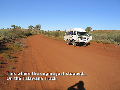
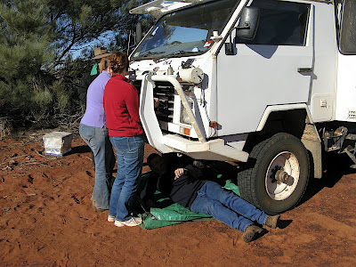
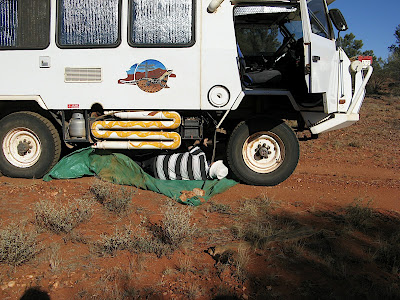
4) The engine just stopped dead on the Talawana Track, near the Rudall River National Park, not the most populated part of the country.

This always leaves a sinking feeling in the pit of your stomach, but fortunately the problem was only a broken wire to the fuel cut off solenoid on the injector pump. The fix was relatively simple, but rejoining the wires was particularly difficult on a very hot engine and caused several blisters on my arm.


And as luck would have it, there was a perfect camping spot just 100 m further on, in a grove of Desert Oaks.

5) The hinge on our fridge door broke.

This happened as we approached Well 41 on the Canning Stock Route.

It was very hot so we needed the fridge working really well (its a Dometic RM2453T). Strapping the fridge door shut worked for a while but this was very inconvenient so a permanent fix was needed. I couldn't just remove the door without the food getting warm so I taped a sheet of plastic over the open fridge to keep the cool air inside as much as possible and removed the door.

The plastic hinge had completely broken in half but I have a lot of confidence in Super Glue. So I glued the broken parts back together and for good measure I glued a piece of aluminium angle along both sides of the broken hinge. For extra good measure, I also screwed the angle to the hinge to add mechanical support. (Note to self: when drilling holes in angles, offset them slightly so the screw threads don't meet in the middle).


Since refitting the hinge we have done 5000 kms of desert tracks without any more problems. Even better, the fix is invisible from the outside so there are no domestic concerns.

However, we don't carry heavy bottles in the door compartments anymore.

6) Both rear axle oil seals leaked.

I replaced one in Katherine (there is a good source of parts there called Car Parts) and left the other one until we got home. It took about 1/2 a day and was quite straight forward, if you have:
  • a replacement oil seal,
  • a big box spanner (2 1/2 inch) to remove the bearing nuts,
  • a tube of gasket replacement to seal the hub flange,
  • Loctite for re-fixing the hub bolts,
  • spare diff oil,
  • a G-clamp for holding the calliper piston in, and
  • preferably a replacement bearing lock washer, although there will probably be plenty of unused tabs on the old one, if it's not worn oval.
      To remove the old oil seal, you can use a cold chisel and hammer to puncture the seal body and lever it out all mangled up, or use an inside gear puller, pushing against a metal bar placed across the disk rotor, and pull the seal out, all mangled up. Either way it will be all mangled up.

      There was some fair wear grooves on the shaft surface caused by the oil seal which I could do nothing about when on the road, but I'm currently considering Speedi Sleeves from CBC Bearings (part number CR99303) to repair the worn surfaces. You'll need the .625 inch (15.875 mm) wide version, but even that protrudes about 25 thou, which will touch the bearing shell, and they are expensive, around $70 each.

      I've since decided not to fit the Speedi Sleeve now, but to keep it in reserve in case either of the rear oil seals go again in a big way and I have to do another fix on the road somewhere. The rear wheel bearings run in oil provided from the differential housing along the axle tube so any substantial leak could cause the bearings to run dry. The diff would probably be OK due to the well beneath the crown gear which holds a fair amount of oil but it does get distributed around the inside of the housing as the crown wheel rotates.

      7) A brake calliper spring clip went missing.

      While we were replacing the broken spring bolt, I noticed that the spring clip on the brake calliper key was missing, which causes the calliper to rattle, and potentially to fall off. Fortunately our callipers are fitted with a retention strap bolted across the key to ensure that both halves of the calliper are held together.


      I didn't have a spare spring clip but I found that a 10 mm tent peg was the right size and could be tapped into the space where the clip should have been. I bent the end of the peg slightly so that it couldn't slide out and it is still there, 5000 kms and many outback tracks later, pending the acquisition of a new key and spring clip. If you do something similar, ensure that the tent peg or whatever, can't foul the wheel or the disk rotor as they rotate.

      The keys themselves can wear and allow the callipers to rattle so it's worth replacing them as well as the spring clips.

      8) The alternator belt burnt out.

      We have a Bosch 120 amp alternator and I had recently fitted a Smart Alternator Regulator (Sterling AR12VD) to charge three batteries. Since this regulator enables the full output from the alternator to be obtained, it also requires a much higher input power (about 2 HP), all of which must be supplied by the alternator belt.

      If the alternator belt is allowed to slip (or is out of alignment), it will quickly overheat and burn out. The standard method for adjusting the alternator belt tension on an Oka is a primitive device which is difficult to tighten and will inevitably slip loose. When we got home, I built a better tensioner using a tapped rod and nuts with which to adjust the tension. We can now achieve middle "C" twanginess, and clamp it in that position, and since then we have had no problems with slipping belts.


      I note that Tim Forsyth in Weipa is fitting twin pulleys and belts on his alternator to address this problem.


      9) The computer keyboard stopped working.

      Although this is not an Oka issue, it did cause us some grief. We were at Well 25 on the Canning Stock Route, having just repaired the rear wheel carrier after I accidentally reversed into a tree (which is another story).

      We have 2 computers on board, networked together. A laptop PC (minus display) to run GPS software and a Mac Mini for everything else, including displaying the moving map navigation data, playing music, TV, movies and downloading our photos.

      The wireless keyboard on the Mac Mini lost its connection to the computer due to low batteries and since I had stupidly set things up to require a password to log in (to safeguard our confidential information in case of theft), I could no longer log in to re-pair the keyboard with the computer. Catch-22. I tried everything, even a remote log in from the laptop, but the security features were just too good.

      Fortunately I was able to download our photos to the laptop, and rewired the LCD display to run from the laptop for navigation, but we had to wait until the next computer shop in Newman, 2 weeks away, before I could buy a cheap USB keyboard and log in to the Mac Mini again. This has also happened again since we arrived home so there is a lesson here about wireless devices. This was not a computer fault as such, just lack of foresight and planning.

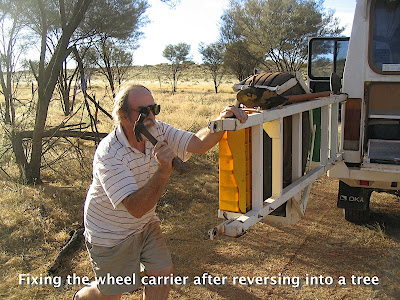
      10) I reversed into tree at Well 25 on the CSR.

      It was only a small mulga tree but it was surprisingly hard and resilient. I only tapped it gently (I thought) but it was sufficient to bend the gate latch straps holding the rear wheel carrier to the vertical support and jammed the gate shut.


      I forced it open by releasing the bolts holding the straps to the gate, and hammered the plates reasonably flat so they no longer bound on the mounting bushes. I then noticed that the lower hinge pin bush, which I had previously fitted to improve the stability of the gate, had dropped out so that the gate was rattling badly.

      I made a new bush from an old shock absorber bush, which proved to be very difficult to cut, being tempered steel. I then drilled both hinge pins and fitted "R" pins to to prevent the bushes from falling out again. That fix has lasted 15,000 kms so far.

      11) Leaking Injector Pump

      In Katherine we noticed that our injector pump had a leak from the rear distributor housing, presumably the "O" ring has hardened. It was not gushing out, only a drip every 2-3 seconds, but enough to be annoying and leave a small puddle on the road when stopped.

      Based on advice received, we tried FashLube in the fuel at double the recommended dose, and used Bio-Diesel fuel when available, to reduce the leakage rate. These are supposed to rejuvenate and expand the rubber "O" ring seals, and they worked to some extent but did not fixed the problem entirely. I was assured that the pump would not fail and leave us stranded, but I fear that only a complete pump overhaul will fully solve the problem.

      To determine exactly how much fuel we were loosing, I made up a funnel from the top section of an old diff oil container and fixed it to the injector pump bracket so that all the drips fell inside it. I then fitted a tube to the spout in the cap and led this to a 4 L oil container which I mounted on a bracket behind the mud flap, below the level of the pump. This worked fine and no drips escaped the collection system.

      Over the next 5,000 kms (down the CSR and Gary/Gunbarrel Highways to Adelaide) we collected about 6 L of fuel, which translates to about a 1% fuel loss. It looked a lot worse than that but we didn't notice any significant impact on the fuel consumption calculations, it still did about 7 km/L overall which is pretty good.

      12) Broken Bolt on Front Bull Bar

      The cantilever design of the Oka bull bar places a lot of stress on its fixing bolts, especially over corrugated roads, and especially if you carry heavy items, such as a Hi-Lift Jack on the bull bar as we do.

      So it was inevitable that something would eventually break, and it did, on the Anne Beadell Highway near Dingo Claypan.

      One of the fixing bolts sheared off, allowing the bar to vibrate and place additional strain on the remaining bolts. A repair was needed or it would get worse.

      The bull bar on any 4WD is a heavy and awkward item to handle and the Oka is no exception. Luckily we had a number of fellow travellers to assist in removing the bull bar. We were then able to remove the sheared off bolt shaft by rotating it gently by tapping it round with a sharp centre-punch.
      After about 10 minutes tapping, the bolt was out and I was able to clean out the thread and locate a high tensile bolt to replace it with.


      Relocating the heavy bull bar took several people as in this photo. Genine and Janet holding the bull bar, Craig directing operations in his foreman's hat, David inserting the fixing bolts from underneath and me taking the photos. A picture of technical harmony.

      13) The Front Drive Shaft Came Loose

      Also on the Anne Beadell Highway, there was a sudden and very loud clonking noise from under the front of the car.

      An initial inspection didn't reveal anything wrong with the axle or diff or axle shafts, but the rear of the drive shaft had come loose and was flailing around hitting the transfer box gear linkages as it went. The "U" bolts holding the universal joint on to the transfer box had worked loose allowing the end caps and needle bearings to fall out, which in turn allowed the shaft to disengage with the transfer box.
      Removing the damaged drive shaft
      I took the shaft off and was going to replace the whole UJ unit, but Craig suggested just replacing the end caps from a spare UJ which would be a lot quicker than replacing the whole thing.

      This we did, and with new bolts holding the UJ clamps in place, everything was greased up and we were back on the road within an hour.

      The UJ end caps replaced and held in place with tape
      We also had to do a temporary fix on the damaged gear linkage to get that operational again, but it worked fine and survived a further 12,000 kms without problems.

      Post trip note: The main damage was to the pivot lever on the side of the gearbox which directs the transfer lever action to the transfer box via a ball joint.


      It is a 6mm thick steel lever which was bent severely by the impact of the flailing drive shaft, causing the ball joint to be twisted and the transfer rod to foul the exhaust pipe.

      To repair this lever first meant removal of the front drive shaft. This presented a problem because one of the small UJ U-bolts proved very stubborn to remove and eventually the head became rounded. Finally I welded a small open-ended spanner to the head of the bolt and I was then able to get it moving. However, the bolt would not then turn with the spanner welded on, so it first that had to be ground off before I could finally remove the last bolt.


      Then I could turn my attention to the original problem, straightening the pivot lever. I couldn't remove the pin holding the pivot lever on to the gearbox since it was jammed in the bush, so I straightened the lever by bolting a breaker bar on to the bent end of the lever and levering it upwards against a block of wood between the lever and the chassis.


      I couldn't fully straighten the lever, but it is now positioned so that the ball joint bolt fits without being stressed and the transfer gear rod no longer fouls the exhaust pipe. It doesn't look pretty but it works fine.


      The problem of removing stubborn UJ bolts, or having them work loose in the first place, can be avoided if the recommended torque settings are used.

      From the Hardy Spicer website, I found the following information for the 2 types of UJ fixings on the 1410 drive shaft fitted to the Oka:

      U-bolt type clamp, 20-24 ft-lbs (27-33 Nm),
      Strap type clamp, 25-30 ft-lbs (34-41 Nm). This is the more critical type.

      Note that the strap clamp bolts from Hardy Spicer come pre-loaded with a locking compound, so Loctite or similar should be used with these torque settings.

      Extract from the Hardy Spicer Catalog, part B:1-45.


      14) Worn Spindle Bearing Surfaces

      We were experiencing an annoying vibration from the front axle/wheel area at around 60-70 km/h which I finally (and reluctantly) tracked down to worn front axle spindles which was caused by, or maybe allowed the bearing cups to rotate on the shaft.

      Worn areas of the spindle.

      New spindles are very expensive in Oz so I investigated metal depositing and regrinding options and I found a company in Adelaide (Adelaide Grinding) who replated/metal sprayed the spindles and reground them to the original dimensions, and at much lower cost than replacing them.

      The repair process is documented here.

      15) Broken Tooth on Differential Gear

      While fixing the worn hubs, I decided to change the front diff oil. As the oil drained out, a lump of gear tooth fell into the oil tray.

      Toothache in the front differential.

      As the hubs and brakes and drive shafts were already out, it was the appropriate time to replace the broken gear, and related oil seals as well.

      The rebuilding process is described here.


      16) Part 1: Burnt-Out Alternator Cabling


      Heading for Mareeba, there was a quick burst of electrical burning smell. Not too much, and only for a short time, but we had both noticed it. Shortly afterwards, the ignition light started to flicker and eventually came on permanently. Then the rev counter stopped counting and then the alternator stopped charging.


      Time to investigate. Initially there seemed to be nothing wrong, I did all the basic checks and everything seemed to be fine, so we motored on to a more civilised location to take a more detailed look. We weren't worried about charging the batteries since our solar panels were charging them just fine in the hot Queensland sun.


      After stocking up in Mareeba we stopped for a few maintenance days at Mt Molloy where there is a very good free, but crowded, rest area.


      After taking the drivers seat out and removing the engine side panel I noticed some burnt wires from the alternator which had been tie-wrapped to the air conditioning hoses, themselves tie-wrapped to the chassis.


      They were in a bunch inside some plastic sleeving and thus fairly well hidden from view, and was one of the few areas that I had not previously done any work on.


      Remains of the burnt out alternator wiring
      After removing numerous tie-wraps and cutting off the plastic sleeving, I was faced with a mass of burnt and melted wires. Some were burnt brown but still working, some were just bits of blackened copper wire with no insulation and a couple had disappeared completely, just leaving their terminals and blobs of molten copper.


      The wiring after being sorted out
      It took quite a while to unravel what I had left and what was missing. Fortunately I had an electronic version of the wiring diagrams on my computer and I traced the identifiable  wires and replaced them with new wire and new terminals. But the thin wire from alternator to the rev counter had disappeared completely, so I had to re-run a new wire from the back of the rev counter to the back of the alternator.


      After rechecking and tidying up the new cables I ran the engine and everything  was OK again. It had taken the best part of a day to analyse and fix the wiring but what had caused the problem in the first place?


      The section of burnt cables started where they were bunched closely together in a plastic sleeve (which allowed them to overheat) and ended roughly where they were tie-wrapped to the air conditioner hose near one of the metal ferrules on the hose. These were close to the point where the valves are located to recharge the a/c gas, which we'd had done only a few weeks before.


      What I think had happened was that the edge of the ferrule on the hose had rubbed on the cables and shorted one of them to either another wire, or the chassis. The hose ferrules were not grounded in themselves, they might have also been touching the chassis. Maybe the act of re-gassing the air conditioning had disturbed the wires and hoses and caused a partial penetration of the insulation on some wires, and subsequent vibration had finally caused the short circuit. Since the wires came directly from the alternator connectors and were fairly low current signals there are no fuses to protect them, so we were fortunate that the short circuit was not sufficiently solid to cause damage to the alternator itself.


      The new wiring bunch, kept well clear of the hose ferrules
      Anyway, all was then well but to ensure it couldn't happen again, the new cable bunch was kept well away from the hose ferrules.


      16) Part 2: Relay Problems


      A month or so after the burnt out wiring was fixed another electrical problem emerged.


      Something around the starter motor/alternator area began making a terrible screeching noise whenever the alternator started up and the red ignition light went out.

      The problem went away when I disabled the alternator, which led me to believe it was an alternator bearing or similar. We subsequently had the alternator checked and a faulty regulator replaced but the problem persisted.

      (Actually, to disable the alternator mechanically, I removed the belt and tie-wrapped it to the engine block since it's very difficult to remove completely, being behind the other 2 belts, the a/c compressor and our air compressor).

      I traced the problem eventually (after several days of frustrated investigation) to the start relay behind the drivers seat. This relay became energised randomly, but only after the alternator started generating an output. That caused the starter motor to engage, generating the terrible noise as the gears tried to mesh.

      So initially I swapped the relay with a spare and cleaned up the relay base as the connections were fairly corroded, but it did not fix the problem.

      In view of the burnt out alternator wiring we'd had a month or so earlier, I investigated further in that area and traced the common wire from the relay coil to a faulty crimped terminal a cable form to the dashboard. The terminal look fine, but the wire came out with only a gentle tug and was plainly not making a good connection. When I remade that connection, the start relay problem went way and has never returned.

      But what caused the relay to energise when it wasn't supposed to?

      There are 2 relays on the dedicated battery charging system, the start relay which enables the starter motor when the key is turned, and the charge relay which switches both batteries in parallel for charging when the alternator turns on. I discovered that the the negative ends of both their coils were commoned together and a single wire was then taken in a cable which led to the dashboard, where presumably it was grounded somewhere. That wire happened to be the one which had the fautly connector.

      To explain what was happening, if this common ground wire became disconnected, as it was in our case, both relay coils are then effectively connected in series. A drive signal to the charge relay, which happens when the alternator starts up, then flows through both coils (instead of going directly to ground) and, via the positive end of the start relay coil, to a ground point under the dashboard. That ground point was caused by various parasitic paths in the electrical system but the current flow was sufficient to turn on both the charge and start relays.


      Once the common ground connection was reestablished by fixing the faulty connector, both relays could then work independently again. But why this single connection has to be taken to the dashboard area to be grounded, instead of to a local ground point, remains a mystery.

      Relays ain't Relays

      However, while doing this investigative work, I discovered, by chance, that not all automotive relays are the same.

      There are obvious differences between the 4 in and 5 pin versions, with the 5 pin version having an extra pin for a change over contact, but there are also at least 2 variations on the 4 and 5 pin connections as well. What's is more worrisome is that they are mechanically interchangeable, while being electrically different.

      For example, on the Oka, the relays under the instrument pod are a different configuration to the start relay.

      This document shows the difference between the various types. The "normal" types are A2 and A3, but notice that the A4 types is similar to A3 but with pins 86 and 30 interchanged.


      On page 2 of this Britax document, (a 2mb PDF file on relays from Britax Australia) you'll notice that there are 2 relays which are called "Australian Configuration" versions (RA1240 and RA1240R). These have pins 30 and 86 interchanged.

      The picture below shows a Bosch relay on the left and 4 and 5 pin "Australian" relays (from Jaycar/Dick Smith etc) on the centre and right with pins 30 and 86 reversed.


      Note the relay on the left has pin 86 downwards, the other have pin 30 downwards
      The more you look into automotive relay configurations, the more confusing it becomes. Suffice to say that when buying or changing automotive relays bear this in mind, and in particular, check the orientation of terminals 30 and 86. Using the incorrect version may or may not be damaging, depending on their function, but the wrong type would only work if the circuit has the coil positive (pin 86) and the battery connection (pin 30) connected to the same point. That would be circuit and application dependent.


      The Oka Manual is Wrong


      The circuit diagram for the Dedicated Starting System in the Oka XT Service Manual, Section 10; Electrical, the Oka manual is wrong.


      Figure 2B on page 162 shows the wiring for the Dedicated Starting System but contains some anomalies. The wire from the charge relay contact to the D+ terminal on the Alternator should not be there, and the wire shown from the charge relay coil to the W terminal on the alternator should probably come from the alternator D+ terminal (but see note below).


      The charge relay coil may be driven from the Tacho (W terminal) as per the Oka diagram, I've seen it done before, for a similar purpose, but the tacho output output is a small ac signal tapped from the alternator stator winding, of variable voltage but whose frequency is proportional to the speed of rotation of the stator and hence the engine RPM. I doubt that it is intended to drive a dc relay coil.


      However, the seed curent for starting the alternator comes through the alternator warning light. If it were driving a relay as well, insufficient current may be available to kick start the alternator. When I had the charge relay connected this way, start up of the alternator was very temperature dependent, OK in the tropics but not in Adelaide. I've now reverted to driving the charge relay from the tacho output. It works but doesn't seem to be a good idea.


      A description of the tacho output from an alternator by Ample Power is shown here).

      BTW, if you ever notice the tacho reading dropping for no apparent reason, it could indicate a slipping belt or wiring problem (eg faulty earth) or a heavily loaded/faulty alternator.


      These errors/anomalies added to the confusion whilst trying to analyse the above problems and a modified version is shown below. 


      Updated wiring diagram for the Dedicated Starting System
      17) Leaking Power Steering Unit


      As we travelled the rough roads across the Gulf Of Carpentaria from Burketown to Booroloola, we noticed a drip from the power steering box. Checking the hydraulic fluid level revealed that the level had gone down about 1 inch. There was nothing that could be done on the side of the road except to top up the reservoir and carry on, mindful of the fact that on a Oka, the power assistance for the brakes also comes from the same hydraulic power source as the steering, so a loss of hydraulic pressure could be quite serious.


      In Booroloola the leak had got worse and was traced to the seal around the input shaft on the top of the steering box. Since we still could not do anything about the leak we reported the problem to our HF Radio network, just in case, and after a long search, bought a 4 litre can of fluid from a  mechanic in Boorloola, the last fluid in the town it would seem.


      Red fluid oozing from the steering box
      During the stretch from Booroloola through the Limmen National Park to Katherine, the leak had stabilised but it was still losing about 250 ml a day, but what was worse was that the fluid dribbled down the outside of the steering box and was then liberally sprayed by the wind over the chassis, springs and eventually down the side of the Oka where of course the dust stuck to it, creating a sticky mess. Something needed to be done.


      In Katherine you can only buy wine in 2 litre casks, and then only with ID and time constraints. Fortunately (stay with me on this) some friends were motoring up from Adelaide to meet us and, forewarned of the alcohol restrictions, were carrying some 5 litres casks of our favourite drop.


      After having some celebratory drinks (after all, we hadn't seen them for 2 years), a cask was empty and the bladder was removed. This, with a corner cut off, directly opposite the tap, made a perfect "bra" to fit over the outside of the leaking steering box and collect the leaking fluid. It was held on by a combination of nylon string, tie-wraps and sticky tape, with the tap hanging downwards.


      Whilst this did not fix the leak, it did solve the fluid dispersion problem and remained in place for the next month until we could get home and plan the replacement of the leaking seal. (See here for details of the fix).


      Each day I topped up the reservoir, and in doing so was able to keep a check on the rate of fluid loss, and drained the fluid from the "bra" into a container, not for reuse, although it could have been filtered for reuse if desperate, but to keep things clean and tidy. This system worked fine for over a month and 5,000 km.


      It's now been fixed and all is well again See this write up.

      18) Engine Cover Insulation Came Adrift


      We've doubled the thickness of sound (and heat) insulation on the underside of the engine cover using this material (note Whitworths also now have thicker and more expensive material available). This works fine, especially in conjunction with the sound proofing on all the other metal surfaces in the cabin.


      However the weight of the insulation caused it to hang down and eventually it became substantially detached from the cover and was resting on the engine rocker box. Since the insulation foil is electrically conductive, this is not a good thing to happen around electrical items either, quite apart from disrupting the air flow around the engine.


      A quick and simple fix (which has also lasted several years) is to fit 2 (or more) lengths of aluminium strip, 25mm wide by 3mm thick, across the inside of the cover. The ends must be bent up to form lips which can be inserted in the folded side edges of the cover, above the rubber sealing strip. This way the cover, which is quite heavy, doesn't have to be removed and the insulation is no longer dependent on the strength of the adhesive.