Our Oka is our Lifeline

On our outback treks, our Oka is our lifeline.

To fully enjoy our travels, (as in the photo above of a delightful campsite in Lakefield National Park), we need to constrain the risks inherent in outback travel, whilst providing a reasonable degree of travelling comfort.

Like all vehicles that are subject to harsh conditions on rough outback tracks, Oka's need to be well equipped and maintained, and although they are very tough vehicles, they can and do break, hence the need for "Travails", or engaging in painful or laborious effort.

These articles describes some of our travails: how we've fixed failures, avoided problems, and upgraded the facilities on our 4WD Oka motorhome. See the full list of articles in the right sidebar.

Saturday, June 29, 2013

Steering Knuckle Maintenance

The steering knuckles are possibly the most neglected moving part on an Oka. With a bit of regular greasing they are quite reliable and just sit there and rotate in response to the steering wheel while soaking up all the road shocks thrown at them.

But they are fairly critical items and there are potential wear points which need occasional attention:

  • The nylon bushes around the upper king pin gradually wear, allowing the wheels to lean in (negative camber).
  • The bearing race at the bottom of the knuckle supports all the weight of the Oka, and since they sit for long periods in substantially one direction, the rollers can pound grooves in the bearing cup.
  • The grease seals in the top and bottom joints can wear and allow the ingress of water and dust.
  • The "C" ends of the axle tube can deform slightly causing the wheels to show a negative camber (lean inwards at the top).
  • The steering arm holes can be worn oval by loose tie rod ends

These problems can be solved quite effectively with a bit of maintenance at the same time as the wheel bearings are being inspected and repacked with grease. To start the process:

  • Remove the wheel, brake calliper, free wheeling hub, spindle locking nuts and washers.
  • Withdraw the hub and wheel bearings,
  • Remove the spindle, brake calliper plate and dust protector.
  • Remove the top king pin cap (nuts on the RHS or bolts on the LHS steering arm). Loosen nuts/bolts progressively, the caps have strong springs under them.
  • Withdraw the axle shaft to inspect the UJ and inner splines.

IMG_8884-2013-06-29-08-07.JPG-2013-06-29-08-24.jpg

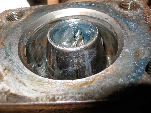
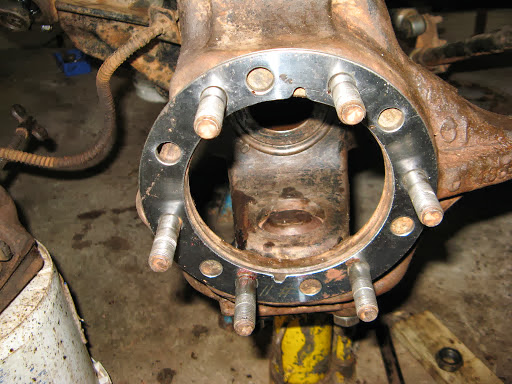
The king pin exposed after removing the top cap, nylon bush and spring.

IMG_8888-2013-06-29-08-07-2013-06-29-08-24.jpg

The top nylon bush with some thinning visible on the top right. This one is only a few years old and will be OK for a few more yet.

After removing steering tie rod, the top cap and lower bearing support, the knuckle can be pulled out at the bottom and fiddled over the king pin. Be careful not to damage its surface.


IMG_1450-2013-06-29-08-07.JPG-2013-06-29-08-24.jpg

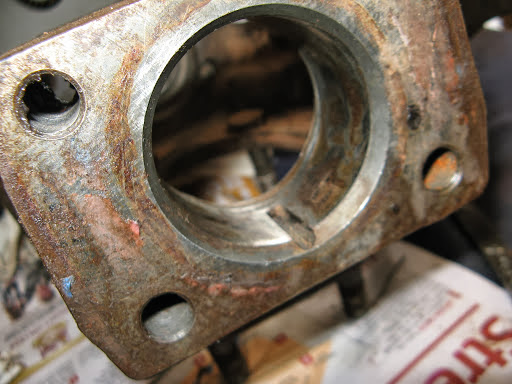
 A dirty “C” end of the axle after removal of the knuckle.

After removing the steering tie rod, the top cap and lower bearing support, the knuckle can be pulled out at the bottom and fiddled over the king pin. Be careful not to damage its surface.

The lower bearing and worn oil seal will probably drop out or can be pulled out after removing the knuckle. The bearing cup and dust cover can be carefully tapped out using a large screw driver around the edges of the dust cover.

IMG_1461-2013-06-29-08-07.JPG-2013-06-29-08-24.jpg

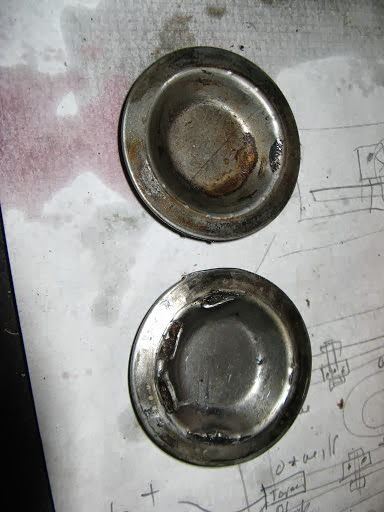
When knocking out the bearing cup, ensure the driver doesn’t slip off the edge of the bearing or it can penetrate the thin dust cover (as in the lower picture). Knock any sharp edges flat and put a smear of gasket goo over the top of the cap after assembly. This will keep water off and prevent rust as well.


IMG_1459-2013-06-29-08-07.JPG-2013-06-29-08-24.jpg

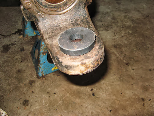
And after being cleaned up a bit and the bearing cup and dust cover removed. If the king pin is still smooth and not rusted or pitted, it can be reused (replacement is apparently only possible by those with super-hero strength anyway).

IMG_1484-2013-06-29-08-07.JPG-2013-06-29-08-24.jpg

Check the inside of the top of the knuckle for wear from the nylon bush.

IMG_1469-2013-06-29-08-07.JPG-2013-06-29-08-24.jpg

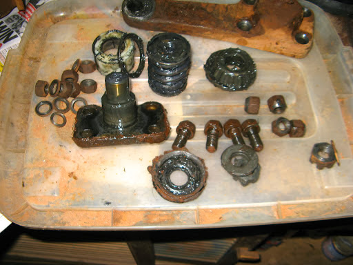
Some of the greasy knuckle components. The top cap on the LHS is part of the steering arm.

IMG_1456-2013-06-29-08-07.JPG-2013-06-29-08-24.jpg

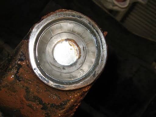
The bearing cup showing signs of wear grooves caused by the pounding of stationary rollers.

IMG_1460-2013-06-29-08-07.JPG-2013-06-29-08-24.jpg

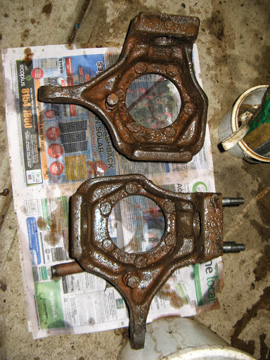
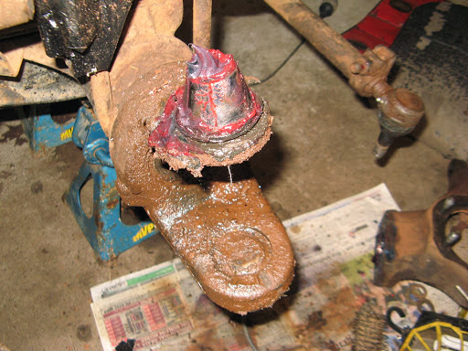
Steering knuckles removed (obviously) and being cleaned of kgs of greasy mud.

IMG_1476-2013-06-29-08-07.JPG-2013-06-29-08-24.jpg

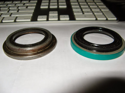
The bearings can be bought locally but the oil/grease seals are very difficult to source locally and may not be the same size, although they still fit.

IMG_1489-2013-06-29-08-07.JPG-2013-06-29-08-24.jpg

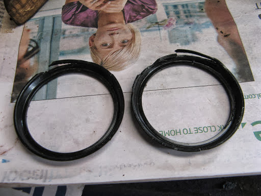
The upper seals are difficult to find but are not too critical . The old ones can be reused if you trim off any tatty edges.

IMG_1478-2013-06-29-08-07.JPG-2013-06-29-08-24.jpg

Hold the dust cover up with a magnet while installing the bearing cup from below.

The bore for the bearing was about 20thou out of round, probably stretched due to the 1/2 million km of stress. I chilled the cup in the freezer but it still needed a lot of heat to expand the arm sufficient to allow the cup to be tapped in from below, open side facing down.

Tapping the cup flush in the arm is OK with a block of hard wood and a hammer, but it needs to be recessed a further 5mm for the oil seal. You can use an old cup as a driver but be careful that it doesn’t get jammed in because it’s a bugga to get out. It probably doesn’t matter if the cup isn’t fully home as the weight of the Oka will push it in and the the top spring and nylon bush will take up any slack.

Fully grease the new bearing and insert it together with the oil seal up behind the bearing cup. The old cup can safely be used for that purpose.

IMG_1487-2013-06-29-08-07.JPG-2013-06-29-08-24.jpg

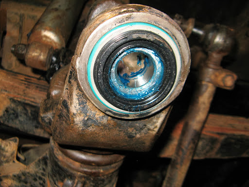
The fully greased bearing and seal refitted into the lower arm.

IMG_1492-2013-06-29-08-07.JPG-2013-06-29-08-24.jpg

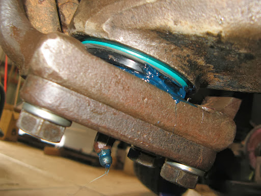
With the knuckle reassembled, check that grease pressure doesn’t start popping the seal out when regreasing the bearing. If it moves, it can be levered back in with a couple of screwdrivers.

IMG_1490-2013-06-29-08-07.JPG-2013-06-29-08-24.jpg

The knuckle reassembly complete. Loctite the top and bottom bolts, fit new spring washers and torque to 80 ft-lbs.

IMG_1503-2013-06-29-08-07.JPG-2013-06-29-08-24.jpg

Because the wheels were leaning in (negative camber) due to slight bending of the “C” ends of the axle tubes, I fitted camber correcting wedges before reinstalling the spindles.

IMG_1508-2013-06-29-08-07.JPG-2013-06-29-08-24.jpg

I also smeared gasket goo over the dust cover to prevent water lying there and causing rust.

IMG_1509-2013-06-29-08-07.JPG-2013-06-29-08-24.jpg

The spindle and camber shim in place.

IMG_1565-2013-06-29-08-07.JPG-2013-06-29-08-24.jpg

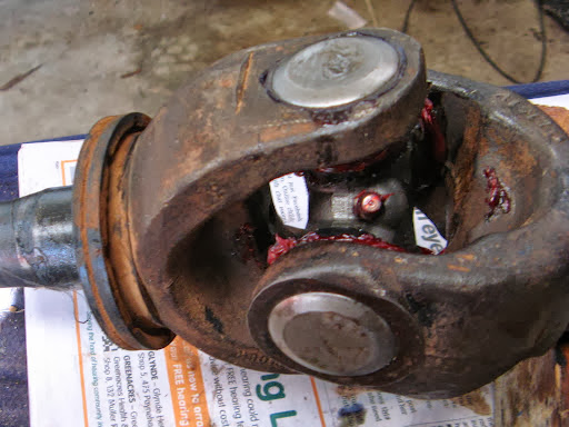
Before reinstalling the axle shaft check and degrease the UJ. These UJ’s take a lot of torque, more than the drive shafts UJ’s due to the 4.88:1 torque multiplication ratio of the differential. The must also transmit that torque while operating at acute steering angles. One of mine was dry and showed signs of wear so it was replaced.

IMG_1507-2013-06-29-08-07.JPG-2013-06-29-08-24.jpg

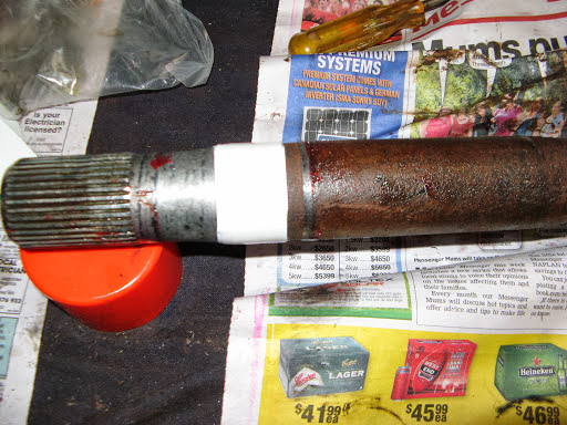
Before installing the axle shaft I cleaned the end and wound a couple of turns of waterproof tape around the shaft in the area that the inner seal lip contacts the shaft. This is to try to reduce the inevitable oil leakage from the diff housing due to stretching of the seal. It might not work but it’s worth a try and certainly easier than replacing the inner seals.

IMG_1065.JPG-2013-06-29-08-24.jpg

Install the axle shaft by sliding it along a length of plastic strip to stop it picking up dirt and transferring it to the diff gears.

IMG_1511-2013-06-29-08-07.JPG-2013-06-29-08-24.jpg

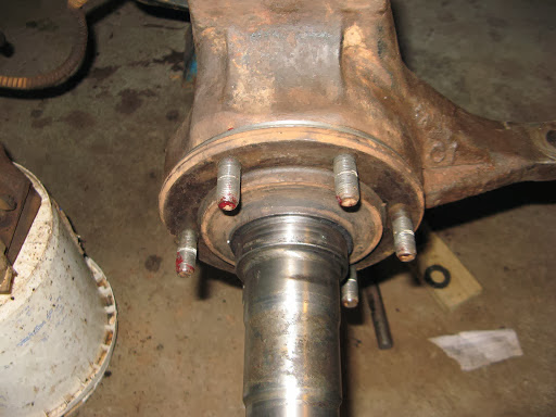
The brake calliper plate, disk protector and spindle back together with nuts Loctited and torqued up to 60ft lbs.

IMG_1557-2013-06-29-08-07.JPG-2013-06-29-08-24.jpg

After repacking the bearings and fitting a new rear hub seal, the hub was reinstalled using my new Stage 8 spindle nuts. The first couple of tries were a bit fiddly but certainly less frustrating than the tabbed washers they replaced, and will make removal of the hub a lot easier in future.

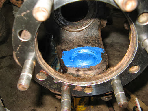
A ring of grease was inserted around the bearing area to reduce the ingress of water.

IMG_1560-2013-06-29-08-07.JPG-2013-06-29-08-24.jpg

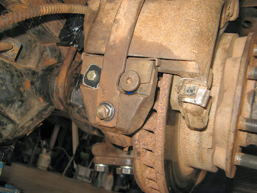
There is provision for 2 bolts on the brake calliper keys in but only one hole in the calliper plate so I drilled and tapped anther hole to add some assurance that the key can’t vibrate loose.

Notes:

1) The thick strap across the calliper is a valuable addition to ensure the calliper can never fall off. It requires fixing holes to be drilled and tapped in the calliper frame.

2) The steel packing pieces around the ends of the brake pads reduce the movement (slop) of the pads when the callipers have worn somewhat.

3) Replace the spring clips under the lower tab of the rear pads to stop them rattling.

IMG_1561-2013-06-29-08-07.JPG-2013-06-29-08-24.jpg

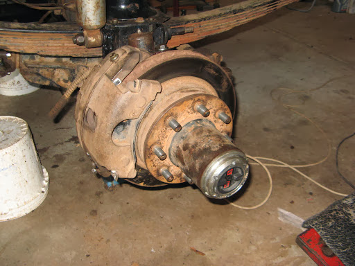
The hub all back together with a free-wheeling hub.

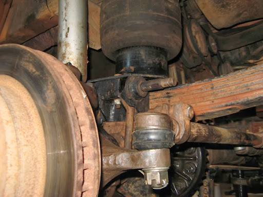
The final task was to reconnect the steering rods, which is a bit tricky since the tie rod hits the bottom of the spring before the bolt can clear the knuckle.

Turning the wheels fully inwards just enables sufficient clearance to be obtained. I also replaced the torn and tattered rubber boots while I was refitting the tie rod ends, and then greased all the joints.

IMG_1562.JPG-2013-06-29-08-24.jpg

One bolt hole in the LHS knuckle had been worn oval shaped due to a loose nut and to fix this I inserted some shim around the bolt and tightened it firmly to hold the shim in place. Eventually the hole will need to be reamed out and a bush fitted to regain the original round tapered shape.

TBC when it’s all back together and tested...

Tuesday, November 13, 2012

Clutch, from Michael Hession, Feb 2004

Clutch Problem - From Michael Hession, Feb 2004:

While we were away in Victoria, just after Christmas, we had to have our clutch replaced. The reason being, the Thrust Bearing failed and damaged the fingers of the clutch pressure plate. The bearing failed due to incorrect free-play adjustment. The clutch face was in good repair, but the pressure plate was unserviceable due to the damaged fingers. Two points that came out of this exercise were:

  1. Clutch Type
  2. Thrust Bearing Free-Play Adjustment.

1. Clutch Type

The standard clutch as fitted to all OKAs is a ceramic clutch and as OKA state in the owners manual, should not be slipped. If you do slip the clutch you will cause rapid wear to the clutch, pressure plate and flywheel. The ceramic clutch was fitted as early testing showed failure of an "organic" clutch. An organic clutch plate is what most people would recognise as a normal clutch plate.

It was recommended by Andrew Kee of Whitehorse Trucks (ex OKA dealers in Morwell, Victoria) that I replace my clutch with an organic type. He had supplied some ten of these to various OKA owners and had had no problems. The advantages being that the clutch can take some slip without undue wear or problems, and it is much softer on the drive-train giving a smoother take-up of the load.

The new NT OKA has an Organic Clutch. I have since learnt that Paul Nott is a good source. The clutch that was fitted to my vehicle is made by Daikin and if you go on their website you will find they have a listing for OKA (WA) and the part numbers start with OK.2. Thrust Bearing Free-Play Adjustment

Terry of Eastside Trucks, Morwell, carried out the repairs to my vehicle. He explained that it is a common problem, that he has found a lot of OKAs have the free play on their clutches incorrectly adjusted. Too often the thrust bearing is under load and therefore working (turning) continuously, leading to early failure of the thrust bearing, or at worst a slipping clutch.To ensure that it is adjusted correctly the following procedure needs to be followed:

        1.        Remove the inspection plate from the bottom of the bell housing (6 screws). Some vehicles will have a grease nipple for greasing the thrust bearing.

        2.        With the plate removed you will be able to see the side of the thrust bearing. With a long screw driver you should be able to freely rotate the bearing with the clutch disengaged.

        3.        If the bearing turns freely, all is good so far. Have someone operate the clutch pedal. As they slowly push the pedal down, you keep on turning the bearing until it stops. At this point the clutch pedal should have moved about 25mm; if so your free-play is adjusted correctly.

        4.        If the bearing does not turn freely, you either have a seized bearing or more likely not enough free play. You will need to adjust the free play by adjusting the adjustment bolt, which is on the opposite side of the bell housing to the clutch lever arm. N.B. Too much free-play will make it difficult to disengage the clutch.

        5.        You will need to test your setting to make sure you can still disengage the clutch.

Saturday, April 7, 2012

Replacing the Rear Seal on the VE Injector Pump

Replacing the Rear Seal on the VE Injector Pump

Background

The injector pump on our Oka developed an annoying minor leak from the rear distributor head several years ago but recently it got suddenly worse and was losing around 200 ml each time it started or stopped, and dripped all the time in between. So it was Time Something Was Done.

The cause of the leak is hardening of the O-ring around the rear distributor head following the removal of sulphur from diesel fuel some 10 years ago. The sulphur acted as a lubricant keep the seals supple and its removal (on good environmental grounds) allowed seals to harden and leak.

b2187456-2012-04-7-08-37.jpg

The hardened (and brittle) O-ring which caused the leak

Removing the pump to replace the seal it is not a trivial job and it got more challenging the further I got into it, but I have now done it successfully and it required only a few spares, some fairly normal tools plus a few days of work.

No really tricky skills are required and anyone with reasonable car maintenance experience could do it. And unless there is something else seriously wrong with the pump, there is no need to go to the expense of a professional rebuild.

I got a lot of useful tips and support from my mate Dave in Perth who was a “transportologist” (truck driver) and has had a lot of experience of injector pumps and diesel engines, including an Oka. So finding someone who knows about injector pumps and/or Okas and can advise you is a well worthwhile. Internet resources may be relevant to the Bosch VE injector pump but they are not likely to be specific to the Perkins engine on an Oka.

Before starting, read all you can find about the VE pump from internet resources, especially the warnings about engine timing and how not to lose it, and ensure you have or can get the item listed below.

Note: If your pump does not have a shaft locking bolt like in the photo below, do a lot more research on engine timing before embarking on this process.

804e8146-2012-04-7-08-37.jpg

You’ll need to locate the shaft lock bolt and its wedge shaped spacer, shown here in the unlocked state

In preparation, you’ll need the following items:

      • A VE pump seal gasket/O-ring set (from a Bosch dealer or the internet using the correct part number of your pump)
      • A pump flange gasket (from a Perkins dealer)
      • Front pump gear cover gasket (from a Perkins dealer or gasket goo can be used)
      • A hydraulic pump O-ring or gasket (gasket goo can be used)
      • Oil filter/cooler mounting gaskets (2) (from a Perkins dealer. Must be new to prevent high pressure oil leaks)
      • Gasket goo (Loctite Blue Maxx)
      • Loctite 423 medium strength thread locker fluid
      • A bolt-on gear puller (needs to be fairly small to fit in the space below the water pump housing and use M8 bolts. I modified a harmonic balancer puller to suit)
      • A 13 mm deep ring spanner you are willing to modify (shorten)
      • Oil filter element (optional but preferable)
      • Fuel filter element (optional but preferable)
      • Digital camera to record the location of components (optional but preferable)
      • A mate like Dave (essential)

Action Plan to Remove the Pump

      • Remove the passengers seat and side engine access panel.
      • Thoroughly degrease and clean the side of the engine, pumps and fuel filter with degreaser.

8c140c71-2012-04-7-08-37.jpg

Access to the pump on our Oka is a bit tricky...

Take plenty of photos of the location of pipes, bolts and cables to aid subsequent reassembly.

      • Move any cables and water pipes aside and hold with tie wraps to provide easier access to the pump area.
      • Mark the top of the pump front cover on the timing case below the water pump housing (for ease of reassembly since it’s asymmetric) and remove the cover.
      • Loosen the drive shaft nut far enough to see the keyway (using a mirror) and ensure that it is pointing upwards. (Note: avoid dropping the nut or lock washer down the front of the timing case. Stuff a rag down there and use a magnetic wand). Put the nut back on if you have to turn the engine to make the keyway upright. It was tightened to 58 ft-lbs.

file-2012-04-7-08-37.jpg

The keyway should be as vertical as practical

      • Disconnect the starter battery to prevent the engine from being turned any more.
      • Lock the pump drive shaft by removing the wedge shaped spacer bar (it has a slot rather than a bolt hole so it can fall out as soon as the bolt is loose), tighten the locking bolt and secure the spacer to the pump throttle lever with wire to remind you to unlock the shaft after reassembly. (Note. Do not turn the engine with this locking bolt engaged, you will damage the pump).
      • Important Note: If your pump does not have a shaft locking bolt, you will need to use a more complex process for ensuring that engine timing is not disturbed and you will need to do more research before embarking on this task.]

d9a21c81-2012-04-7-08-37.jpg

The shaft is now locked and the spacer safely stored away, wired to the throttle lever so it can’t easily be forgotten

      • Mark the fuel direction on the 2 fuel filter pipes from the lift pump and the return to the tank using sticky tape to avoid later confusion.
      • Remove the fuel pipes between the filter and injector pump.
      • Remove the remaining fuel pipes from the top of the injector pump.
      • Remove the fuel filter and bowl behind the pump.
      • Release the throttle cable end from the pump lever.

df21004f-2012-04-7-08-37.jpg

The fuel filter is out but there’s still a long way to go

      • Drain the radiator water but...
      • 167d27de-2012-04-7-08-37.jpg
      • ...don't knock your bucket over
      • Remove the water pipes from the thermostat housing and rear engine block to the oil cooler. This improves side access and allows the oil cooler to be removed later.
      • Remove the high pressure fuel lines from the rear of the injector pump and the injectors on the engine and put aside so that no dirt can enter the pipes.
      • Cover the exposed ports on the injectors and the rear of the pump with tape or screw caps (eg chair tips) to avoid dirt falling in.
      • If there aren’t any timing marks, scribe some on the flange of the injector pump and the timing case to use later as confirmation of correct reassembly.

d95dd855-2012-04-7-08-37.jpg

Scribe timing marks on timing case (this needs one on the flange too)

(Photo courtesy of Mike's 1993 Dodge Cummins Truck Blog).

      • Remove the front drive shaft nut (22 mm socket) and lock washer, being careful not to allow them to drop into the timing case (stuff a cloth between the front of the gear and the timing case and use a magnetic wand). The nut is tightened to 58 ft-lbs.
      • Access to 2 of the 3 pump flange nuts is very difficult, particularly the lower nut which will probably require the hydraulic pump to be withdrawn and moved aside for access (however it’s not necessary to remove any hydraulic pipes).

9bb6e388-2012-04-7-08-37.jpg

The lower flange bolt is actually more difficult to access than it looks

      • Access to the top bolt holding the hydraulic pump on is also very difficult as it is partly hidden below the injector pump and it’s easier if the oil filter/cooler mounting is also removed first. You may need to make up a special tool to remove this bolt as it comes very close to the bottom of the injector pump as its being undone and ring spanner can no longer be used. (If you are lucky someone will have replaced the top bolt with a socket head bolt, as I have now, so that a long Allen key can be used from the rear). My top bolt has a slot cut in it for a screw driver but I didn’t realise what it was for until I had removed it.

24489cfa-2012-04-7-08-37.jpg

Don’t attempt to remove the nearby socket head bolts, they hold the spline bearing case on to the timing case

      • The hydraulic pump will need to be twisted sideways while being withdrawn (and when being replaced) as its top flange will strike the bottom of the injector pump before the splined shaft has cleared the drive gear. You may also have to release the proportioning valve from the front chassis to provide sufficient slack for the hydraulic pipes.
      • Push the pump downwards and out of the way but don’t damage the splines on the engine mount. 
      • Cover the gear opening to avoid dirt falling in.
      • The injector pump is now more accessible.
      • Loosen the top 2 flange nuts most of the way so that when the pump is pushed back it can’t fall off the studs.
      • Remove the lower flange nut. This is the most difficult nut to access of the whole job. It is recessed and difficult to fit a socket on and might require a special tool made up to remove it. I shortened the handle of a deeply offset 13mm ring spanner, since there is limited room to rotate a full length spanner.
      • Whilst it didn’t happen to me, others have experienced the studs coming out of the timing case instead of the nuts unscrewing. In this case they will need to be reinserted minus the nuts and tightened before reassembly.
      • Remove the nut and bolt holding the rear support plate of the pump to the bracket on the engine block. (Note, this is very easily overlooked, as I found).

58c326e2-2012-04-7-08-37.jpg

This bolt is very easy to overlook

4e3916e4-2012-04-7-08-37.jpg

A bolt on gear puller modified to fit under the water pump housing and uses 2 x M8 bolts for attachment to the drive gear

      • Using a bolt-on gear puller, push the pump shaft out of the drive gear. (Do not use a gear puller hooked against the timing case, it will break the case. There are 2 M8 bolt holes in the drive gear for a bolt-on puller.) The drive shaft is tapered and can be very difficult to dislodge. Apply tension to the puller and then give the centre bolt a sharp tap with a mallet to break the joint.
  • Remove the remaining flange nuts and carefully withdraw the injector pump from the rear, ensuring that the woodruff key does not fall out (use a magnetic wand as soon as it’s visible).
  • 88f2916a-2012-04-7-08-37.jpg

    The small woodruff key on the magnetic wand

        • The injector pump is bigger and heavier than it looks (around 6-7 kg) so provide support to ensure that it can’t fall over, or fall off the work bench.

    3dfedba1-2012-04-7-08-37.jpg

    The pump is off, cleaned ready for work

        • Protect the drive shaft threads with a rubber chair tip.
        • After removing the injector pump, the drive gear may appear to have moved. It can roll sideways on the gear teeth but should stay in mesh. Don’t be tempted to relocate it manually, you might loose the engine timing. It can be recentred during refitting of the pump.

    3cb83881-2012-04-7-08-37.jpg

    The drive gear has rolled sideways but will stay meshed. Don’t move it manually

    Resealing the Pump

        • There are a number of internet resources available which describe how to replace the rear O-ring seal on the VE pump, especially this one at http://www.crustycrank.com/resealinjpump.htm#injpump. All of them emphasise that the pump should be held vertically downwards with the distributor head pointing upwards so that as the head is released, no internal parts can drop out of their correct position.
        • I clamped my pump in a small wooden bench vice mounted on top of the workbench for ease of access. Use wooden blocks to avoid damage to the pump when clamped.

    6aace661-2012-04-7-08-37.jpg

    The pump secured vertically in a bench vice

        • Remove the rear support plate on the pump. This is held on (in my case) by a combination of Torx and Allen headed bolts which can be quite tight so avoid damaging the heads during this process. I didn’t need any additional help to remove them but if they won’t loosen easily, a suggestion is to use a a pipe or G clamp to hold the Torx/Allen bit tightly into the bolt head and turn it with a spanner.

    0b1bd1b4-2012-04-7-08-37.jpg

    A clamping method for removing stubborn Torx or Allen headed screws (photo courtesy of crustycrank.com)

        • One of the bolts holding the rear support plate on is also one of the 4 bolts securing the distributor head. Replace that bolt after removing the plate.
        • Remove the fuel cut off solenoid from the distributor head and carefully remove the plunger and its spring.

    d853314a-2012-04-7-08-37.jpg

    The distributor head covered in smooth tape

        • To access the O-ring, the distributor head must be partly (but NOT completely) released.
        • Undo the 4 bolts progressively until you can see the head moving upwards (depending on the position in its cycle when it last stopped, the head may be spring loaded and come up by itself).

    121f5588-2012-04-7-08-37.jpg

    The head only needs to be removed this far

        • Continue to undo the 4 bolts progressively, ensuring that the head is coming up with them, until the O-ring can just be seen but no more. The head may need to be lifted gently to ensure this but don’t allow the head to come completely out. It may not cause any problems but why take the risk?
        • Remove 2 diagonally opposite bolts leaving 2 bolts holding the head in place.
        • Carefully lift and cut the O-ring and remove it but don’t scratch the groove that it sits in. I used a wooden cocktail stick but the O-ring was hard and brittle (which was the cause of the leak) and broke easily.

    98978132-2012-04-7-08-37.jpg

    Replacing the O-ring (photo courtesy of crustycrank.com)

        • Clean the O-ring groove as well as possible.
        • Now the new O-ring can be fitted.
        • Wind some smooth tape around the rough exterior of the distributor head so that the new O-ring is not damaged during fitting, but don’t cover up the bolt heads or holes, access will be needed.
        • Grease the outside of the tape and the new O-ring well and stretch it over the distributor head.
        • Slide the O-ring down until it drops into the gap and carefully manoeuvre it into its groove on 2 sides. It will still be on the outside of the 2 bolts.
        • Reinsert the 2 bolts which were removed so that they hold the head in the same position, being careful not to damage the O-ring on the way.
        • Holding the O-ring away from the threads (I used a cocktail stick), remove the first 2 bolts one at a time and allow the O-ring to slip into the groove.
        • Once the O-ring is fully in its groove, tighten all 4 bolts progressively so the head slides evenly back into its location.
        • Refit the rear support plate.
        • Reinstall the fuel cut off solenoid with the plunger and spring.
        • If no other work is required on the pump, the resealing task is complete and it can be refitted to the Oka by reversing the above process.

    a734dd38-2012-04-7-08-37.jpg

    The injector pump complete and ready for refitting

    Flushing out the Pump (Optional)

        • In my case I also wanted to flush out the inside of the pump since I had previously replaced the throttle shaft and its bush and seal, and wanted to remove any lingering swarf and dirt that may have been left in the pump body from that process. Since I did that job without removing the pump, I could not easily flush it out at the time.
          • To do this you will also need a rectangular top cover gasket which probably came with the gasket/O-ring set.
          • Removing the top cover is fairly straightforward but the throttle linkage inside needs to be removed carefully. It is also a bit tricky to replace when putting the cover back on and this blog entry explains how to do that.
          • I used the lift pump lever to pump some clean filtered diesel into a container to flush out the pump and then refilled the pump with clean diesel before refitting the top cover to make subsequent priming of the system a bit easier.
          • While it was empty, I also checked inside to ensure that no components had moved or fallen out during the resealing process.

    748b4baa-2012-04-7-08-37.jpg

    Checking the internals of the pump

    Reassembly Notes

        • Use Loctite on all major bolts and nuts, as in my case none of them had spring washers or nyloc nuts and you don’t want these critical parts to come loose.
        • Clean everything well before reassembly, especially oil passages where dirt or bits of hardened gasket may have lodged.
        • Refit the hydraulic pump by twisting it sideways while holding the splines level to mate with the drive gear. Use a M8 socket head screw in the top bolt hole and a long Allen key to tighten it from the rear.

    a05f77a2-2012-04-7-08-37.jpg

    The hydraulic pump refitted with a socket head screw

        • I replaced the oil filter element since it need one anyway and the oil filter mounting was easier to replace without the filter attached. In my case the block on the side of the engine did not detach so I didn’t need to replace its gasket.

    3f853772-2012-04-7-08-37.jpg

    Oil filter/cooler mounting refitted

        • I also replaced the element in the fuel filter and cleaned out the bowl while it was out.
        • When refitting the injector pump, ensure that the woodruff key is well seated in its slot and can’t easily get knocked out.
        • To re-centre the pump drive gear, insert an M8 bolt into the front of the gear and using a rubber strap, gently pull and secure the gear across the engine so that the centre hole is approximately central in the opening and the keyway is upright. The tapered shaft on the pump will then automatically centre it correctly.
        • Check that the timing marks scribed earlier still line up before tightening the flange nuts.
        • Double check that the shaft lock bolt on the injector pump has been reset and the spacer refitted before attempting to turn the engine.
        • Torque the drive shaft nut, with a new lock washer, to 58 ft-lbs. I also checked visually that the woodruff key was actually in the slot before finally tightening the nut.
        • Note that the pump drive gear cover is asymmetric and only fits one way round.

    Priming the System

        • Loosen the banjo nut on top of the fuel filter and use the priming lever on the lift pump to fill the bowl until fuel comes out of the banjo nut, then retighten it.
        • If you are replacing the oil filter, refill the element with around a litre of oil before refitting it, to aid the re-priming of the oil system.
        • Switch off or disconnect the lead to the fuel cut off solenoid on the injector pump and spin the engine until the oil pressure comes up before actually starting the engine (a good idea even if you haven’t just resealed the injector pump.
        • Don’t forget to refill the radiator and check for water leaks.

    Testing the System

    b804606e-2012-04-7-08-37.jpg

    Everything back in place ready for testing

        • Loosen the injector nozzle nuts on cylinders 2 and 3 slightly to allow air trapped in the injector pump to be cleared after the engine first starts. A mist of diesel will squirt out so keep clear of the injectors. After about 10 seconds, stop the engine and tighten the nuts.
        • My engine fired immediately and ran fairly smoothly during this process but ran very smoothly after tightening the injector nozzles.
        • If for any reason something goes wrong and the engine over revs, there is a mechanical "stop engine" lever on the side of the pump.

    7d16e917-2012-04-7-08-37.jpg

    Mechanical Engine Stop Lever

        • Subsequent test runs showed no signs of the original fuel leak.
        • Recheck the water level after a few test runs and the task is complete.

    Post Completion Note:


    About 2 weeks after the rear seal was replaced, a quite severe leak developed around the top cover of the pump. This was very annoying, meaning that the top cover had to be removed again. The cause was found to be an undersized o-ring seal around the top cover. 

    • 01671c26-2012-04-7-08-37.jpg
  • On the left, the seal which leaked after 2 weeks. Note that is is much thinner than the new seal on the right.
  • How this came to be in my overhaul kit remains a mystery as it's the same shape as the original, and the new seals, but was much thinner, accounting for the leak.

    b733069e-2012-04-7-08-37.jpg

    The thinner, leaking seal is in the centre and the others are full size seals

    When replacing the top cover seal, ensure that you have the correct size for your pump to avoid an unnecessary secondary rebuild. It's much more difficult replacing the top cover seal with the pump attached to the engine than on the bench. See here for how it can be done.


    If this leak had occurred after leaving for a long outback trip it would have been extremely frustrating.

    While the top cover was off, I also replaced the Stop Lever seal and the throttle shaft seal.

    I found MTQ Diesels in Adelaide very useful for the supply of Bosch seals and overhaul kits, and quite economical. The Bosch part numbers are:

    1. Repair seal kit, 1 467 010 059, $22.00. This contains all the rubber seals, copper washers and screw caps to overhaul the pump (but no instructions). If you need to replace the throttle shaft and its press-in bush due to wear, order those items separately.
    2. Top cover o-ring seal, 1 461 015 302, $4.00. I bought a spare top cover o-ring seal in addition to the one in the kit.

    Epilogue:

    I completed the above resealing of the injector pump in April 2012.

    During June to September we did a 13,000km trek across the desert tracks of WA, NT and SA (see here for details) and I'm pleased to say we had no leaks from the injector pump and engine performance was at least as good as before and maybe a bit better at the top end.

    The fully loaded Oka would cruise at 90kph when required whereas previously it wasn't very happy above 80kph.

    Overall fuel consumption was a tick over 6.5km/l.

    David Ribbans, April 2012