Our Oka is our Lifeline

On our outback treks, our Oka is our lifeline.

To fully enjoy our travels, (as in the photo above of a delightful campsite in Lakefield National Park), we need to constrain the risks inherent in outback travel, whilst providing a reasonable degree of travelling comfort.

Like all vehicles that are subject to harsh conditions on rough outback tracks, Oka's need to be well equipped and maintained, and although they are very tough vehicles, they can and do break, hence the need for "Travails", or engaging in painful or laborious effort.

These articles describes some of our travails: how we've fixed failures, avoided problems, and upgraded the facilities on our 4WD Oka motorhome. See the full list of articles in the right sidebar.

Tuesday, November 13, 2012

Clutch, from Michael Hession, Feb 2004

Clutch Problem - From Michael Hession, Feb 2004:

While we were away in Victoria, just after Christmas, we had to have our clutch replaced. The reason being, the Thrust Bearing failed and damaged the fingers of the clutch pressure plate. The bearing failed due to incorrect free-play adjustment. The clutch face was in good repair, but the pressure plate was unserviceable due to the damaged fingers. Two points that came out of this exercise were:

  1. Clutch Type
  2. Thrust Bearing Free-Play Adjustment.

1. Clutch Type

The standard clutch as fitted to all OKAs is a ceramic clutch and as OKA state in the owners manual, should not be slipped. If you do slip the clutch you will cause rapid wear to the clutch, pressure plate and flywheel. The ceramic clutch was fitted as early testing showed failure of an "organic" clutch. An organic clutch plate is what most people would recognise as a normal clutch plate.

It was recommended by Andrew Kee of Whitehorse Trucks (ex OKA dealers in Morwell, Victoria) that I replace my clutch with an organic type. He had supplied some ten of these to various OKA owners and had had no problems. The advantages being that the clutch can take some slip without undue wear or problems, and it is much softer on the drive-train giving a smoother take-up of the load.

The new NT OKA has an Organic Clutch. I have since learnt that Paul Nott is a good source. The clutch that was fitted to my vehicle is made by Daikin and if you go on their website you will find they have a listing for OKA (WA) and the part numbers start with OK.2. Thrust Bearing Free-Play Adjustment

Terry of Eastside Trucks, Morwell, carried out the repairs to my vehicle. He explained that it is a common problem, that he has found a lot of OKAs have the free play on their clutches incorrectly adjusted. Too often the thrust bearing is under load and therefore working (turning) continuously, leading to early failure of the thrust bearing, or at worst a slipping clutch.To ensure that it is adjusted correctly the following procedure needs to be followed:

        1.        Remove the inspection plate from the bottom of the bell housing (6 screws). Some vehicles will have a grease nipple for greasing the thrust bearing.

        2.        With the plate removed you will be able to see the side of the thrust bearing. With a long screw driver you should be able to freely rotate the bearing with the clutch disengaged.

        3.        If the bearing turns freely, all is good so far. Have someone operate the clutch pedal. As they slowly push the pedal down, you keep on turning the bearing until it stops. At this point the clutch pedal should have moved about 25mm; if so your free-play is adjusted correctly.

        4.        If the bearing does not turn freely, you either have a seized bearing or more likely not enough free play. You will need to adjust the free play by adjusting the adjustment bolt, which is on the opposite side of the bell housing to the clutch lever arm. N.B. Too much free-play will make it difficult to disengage the clutch.

        5.        You will need to test your setting to make sure you can still disengage the clutch.

Saturday, April 7, 2012

Replacing the Rear Seal on the VE Injector Pump

Replacing the Rear Seal on the VE Injector Pump

Background

The injector pump on our Oka developed an annoying minor leak from the rear distributor head several years ago but recently it got suddenly worse and was losing around 200 ml each time it started or stopped, and dripped all the time in between. So it was Time Something Was Done.

The cause of the leak is hardening of the O-ring around the rear distributor head following the removal of sulphur from diesel fuel some 10 years ago. The sulphur acted as a lubricant keep the seals supple and its removal (on good environmental grounds) allowed seals to harden and leak.

b2187456-2012-04-7-08-37.jpg

The hardened (and brittle) O-ring which caused the leak

Removing the pump to replace the seal it is not a trivial job and it got more challenging the further I got into it, but I have now done it successfully and it required only a few spares, some fairly normal tools plus a few days of work.

No really tricky skills are required and anyone with reasonable car maintenance experience could do it. And unless there is something else seriously wrong with the pump, there is no need to go to the expense of a professional rebuild.

I got a lot of useful tips and support from my mate Dave in Perth who was a “transportologist” (truck driver) and has had a lot of experience of injector pumps and diesel engines, including an Oka. So finding someone who knows about injector pumps and/or Okas and can advise you is a well worthwhile. Internet resources may be relevant to the Bosch VE injector pump but they are not likely to be specific to the Perkins engine on an Oka.

Before starting, read all you can find about the VE pump from internet resources, especially the warnings about engine timing and how not to lose it, and ensure you have or can get the item listed below.

Note: If your pump does not have a shaft locking bolt like in the photo below, do a lot more research on engine timing before embarking on this process.

804e8146-2012-04-7-08-37.jpg

You’ll need to locate the shaft lock bolt and its wedge shaped spacer, shown here in the unlocked state

In preparation, you’ll need the following items:

      • A VE pump seal gasket/O-ring set (from a Bosch dealer or the internet using the correct part number of your pump)
      • A pump flange gasket (from a Perkins dealer)
      • Front pump gear cover gasket (from a Perkins dealer or gasket goo can be used)
      • A hydraulic pump O-ring or gasket (gasket goo can be used)
      • Oil filter/cooler mounting gaskets (2) (from a Perkins dealer. Must be new to prevent high pressure oil leaks)
      • Gasket goo (Loctite Blue Maxx)
      • Loctite 423 medium strength thread locker fluid
      • A bolt-on gear puller (needs to be fairly small to fit in the space below the water pump housing and use M8 bolts. I modified a harmonic balancer puller to suit)
      • A 13 mm deep ring spanner you are willing to modify (shorten)
      • Oil filter element (optional but preferable)
      • Fuel filter element (optional but preferable)
      • Digital camera to record the location of components (optional but preferable)
      • A mate like Dave (essential)

Action Plan to Remove the Pump

      • Remove the passengers seat and side engine access panel.
      • Thoroughly degrease and clean the side of the engine, pumps and fuel filter with degreaser.

8c140c71-2012-04-7-08-37.jpg

Access to the pump on our Oka is a bit tricky...

Take plenty of photos of the location of pipes, bolts and cables to aid subsequent reassembly.

      • Move any cables and water pipes aside and hold with tie wraps to provide easier access to the pump area.
      • Mark the top of the pump front cover on the timing case below the water pump housing (for ease of reassembly since it’s asymmetric) and remove the cover.
      • Loosen the drive shaft nut far enough to see the keyway (using a mirror) and ensure that it is pointing upwards. (Note: avoid dropping the nut or lock washer down the front of the timing case. Stuff a rag down there and use a magnetic wand). Put the nut back on if you have to turn the engine to make the keyway upright. It was tightened to 58 ft-lbs.

file-2012-04-7-08-37.jpg

The keyway should be as vertical as practical

      • Disconnect the starter battery to prevent the engine from being turned any more.
      • Lock the pump drive shaft by removing the wedge shaped spacer bar (it has a slot rather than a bolt hole so it can fall out as soon as the bolt is loose), tighten the locking bolt and secure the spacer to the pump throttle lever with wire to remind you to unlock the shaft after reassembly. (Note. Do not turn the engine with this locking bolt engaged, you will damage the pump).
      • Important Note: If your pump does not have a shaft locking bolt, you will need to use a more complex process for ensuring that engine timing is not disturbed and you will need to do more research before embarking on this task.]

d9a21c81-2012-04-7-08-37.jpg

The shaft is now locked and the spacer safely stored away, wired to the throttle lever so it can’t easily be forgotten

      • Mark the fuel direction on the 2 fuel filter pipes from the lift pump and the return to the tank using sticky tape to avoid later confusion.
      • Remove the fuel pipes between the filter and injector pump.
      • Remove the remaining fuel pipes from the top of the injector pump.
      • Remove the fuel filter and bowl behind the pump.
      • Release the throttle cable end from the pump lever.

df21004f-2012-04-7-08-37.jpg

The fuel filter is out but there’s still a long way to go

      • Drain the radiator water but...
      • 167d27de-2012-04-7-08-37.jpg
      • ...don't knock your bucket over
      • Remove the water pipes from the thermostat housing and rear engine block to the oil cooler. This improves side access and allows the oil cooler to be removed later.
      • Remove the high pressure fuel lines from the rear of the injector pump and the injectors on the engine and put aside so that no dirt can enter the pipes.
      • Cover the exposed ports on the injectors and the rear of the pump with tape or screw caps (eg chair tips) to avoid dirt falling in.
      • If there aren’t any timing marks, scribe some on the flange of the injector pump and the timing case to use later as confirmation of correct reassembly.

d95dd855-2012-04-7-08-37.jpg

Scribe timing marks on timing case (this needs one on the flange too)

(Photo courtesy of Mike's 1993 Dodge Cummins Truck Blog).

      • Remove the front drive shaft nut (22 mm socket) and lock washer, being careful not to allow them to drop into the timing case (stuff a cloth between the front of the gear and the timing case and use a magnetic wand). The nut is tightened to 58 ft-lbs.
      • Access to 2 of the 3 pump flange nuts is very difficult, particularly the lower nut which will probably require the hydraulic pump to be withdrawn and moved aside for access (however it’s not necessary to remove any hydraulic pipes).

9bb6e388-2012-04-7-08-37.jpg

The lower flange bolt is actually more difficult to access than it looks

      • Access to the top bolt holding the hydraulic pump on is also very difficult as it is partly hidden below the injector pump and it’s easier if the oil filter/cooler mounting is also removed first. You may need to make up a special tool to remove this bolt as it comes very close to the bottom of the injector pump as its being undone and ring spanner can no longer be used. (If you are lucky someone will have replaced the top bolt with a socket head bolt, as I have now, so that a long Allen key can be used from the rear). My top bolt has a slot cut in it for a screw driver but I didn’t realise what it was for until I had removed it.

24489cfa-2012-04-7-08-37.jpg

Don’t attempt to remove the nearby socket head bolts, they hold the spline bearing case on to the timing case

      • The hydraulic pump will need to be twisted sideways while being withdrawn (and when being replaced) as its top flange will strike the bottom of the injector pump before the splined shaft has cleared the drive gear. You may also have to release the proportioning valve from the front chassis to provide sufficient slack for the hydraulic pipes.
      • Push the pump downwards and out of the way but don’t damage the splines on the engine mount. 
      • Cover the gear opening to avoid dirt falling in.
      • The injector pump is now more accessible.
      • Loosen the top 2 flange nuts most of the way so that when the pump is pushed back it can’t fall off the studs.
      • Remove the lower flange nut. This is the most difficult nut to access of the whole job. It is recessed and difficult to fit a socket on and might require a special tool made up to remove it. I shortened the handle of a deeply offset 13mm ring spanner, since there is limited room to rotate a full length spanner.
      • Whilst it didn’t happen to me, others have experienced the studs coming out of the timing case instead of the nuts unscrewing. In this case they will need to be reinserted minus the nuts and tightened before reassembly.
      • Remove the nut and bolt holding the rear support plate of the pump to the bracket on the engine block. (Note, this is very easily overlooked, as I found).

58c326e2-2012-04-7-08-37.jpg

This bolt is very easy to overlook

4e3916e4-2012-04-7-08-37.jpg

A bolt on gear puller modified to fit under the water pump housing and uses 2 x M8 bolts for attachment to the drive gear

      • Using a bolt-on gear puller, push the pump shaft out of the drive gear. (Do not use a gear puller hooked against the timing case, it will break the case. There are 2 M8 bolt holes in the drive gear for a bolt-on puller.) The drive shaft is tapered and can be very difficult to dislodge. Apply tension to the puller and then give the centre bolt a sharp tap with a mallet to break the joint.
  • Remove the remaining flange nuts and carefully withdraw the injector pump from the rear, ensuring that the woodruff key does not fall out (use a magnetic wand as soon as it’s visible).
  • 88f2916a-2012-04-7-08-37.jpg

    The small woodruff key on the magnetic wand

        • The injector pump is bigger and heavier than it looks (around 6-7 kg) so provide support to ensure that it can’t fall over, or fall off the work bench.

    3dfedba1-2012-04-7-08-37.jpg

    The pump is off, cleaned ready for work

        • Protect the drive shaft threads with a rubber chair tip.
        • After removing the injector pump, the drive gear may appear to have moved. It can roll sideways on the gear teeth but should stay in mesh. Don’t be tempted to relocate it manually, you might loose the engine timing. It can be recentred during refitting of the pump.

    3cb83881-2012-04-7-08-37.jpg

    The drive gear has rolled sideways but will stay meshed. Don’t move it manually

    Resealing the Pump

        • There are a number of internet resources available which describe how to replace the rear O-ring seal on the VE pump, especially this one at http://www.crustycrank.com/resealinjpump.htm#injpump. All of them emphasise that the pump should be held vertically downwards with the distributor head pointing upwards so that as the head is released, no internal parts can drop out of their correct position.
        • I clamped my pump in a small wooden bench vice mounted on top of the workbench for ease of access. Use wooden blocks to avoid damage to the pump when clamped.

    6aace661-2012-04-7-08-37.jpg

    The pump secured vertically in a bench vice

        • Remove the rear support plate on the pump. This is held on (in my case) by a combination of Torx and Allen headed bolts which can be quite tight so avoid damaging the heads during this process. I didn’t need any additional help to remove them but if they won’t loosen easily, a suggestion is to use a a pipe or G clamp to hold the Torx/Allen bit tightly into the bolt head and turn it with a spanner.

    0b1bd1b4-2012-04-7-08-37.jpg

    A clamping method for removing stubborn Torx or Allen headed screws (photo courtesy of crustycrank.com)

        • One of the bolts holding the rear support plate on is also one of the 4 bolts securing the distributor head. Replace that bolt after removing the plate.
        • Remove the fuel cut off solenoid from the distributor head and carefully remove the plunger and its spring.

    d853314a-2012-04-7-08-37.jpg

    The distributor head covered in smooth tape

        • To access the O-ring, the distributor head must be partly (but NOT completely) released.
        • Undo the 4 bolts progressively until you can see the head moving upwards (depending on the position in its cycle when it last stopped, the head may be spring loaded and come up by itself).

    121f5588-2012-04-7-08-37.jpg

    The head only needs to be removed this far

        • Continue to undo the 4 bolts progressively, ensuring that the head is coming up with them, until the O-ring can just be seen but no more. The head may need to be lifted gently to ensure this but don’t allow the head to come completely out. It may not cause any problems but why take the risk?
        • Remove 2 diagonally opposite bolts leaving 2 bolts holding the head in place.
        • Carefully lift and cut the O-ring and remove it but don’t scratch the groove that it sits in. I used a wooden cocktail stick but the O-ring was hard and brittle (which was the cause of the leak) and broke easily.

    98978132-2012-04-7-08-37.jpg

    Replacing the O-ring (photo courtesy of crustycrank.com)

        • Clean the O-ring groove as well as possible.
        • Now the new O-ring can be fitted.
        • Wind some smooth tape around the rough exterior of the distributor head so that the new O-ring is not damaged during fitting, but don’t cover up the bolt heads or holes, access will be needed.
        • Grease the outside of the tape and the new O-ring well and stretch it over the distributor head.
        • Slide the O-ring down until it drops into the gap and carefully manoeuvre it into its groove on 2 sides. It will still be on the outside of the 2 bolts.
        • Reinsert the 2 bolts which were removed so that they hold the head in the same position, being careful not to damage the O-ring on the way.
        • Holding the O-ring away from the threads (I used a cocktail stick), remove the first 2 bolts one at a time and allow the O-ring to slip into the groove.
        • Once the O-ring is fully in its groove, tighten all 4 bolts progressively so the head slides evenly back into its location.
        • Refit the rear support plate.
        • Reinstall the fuel cut off solenoid with the plunger and spring.
        • If no other work is required on the pump, the resealing task is complete and it can be refitted to the Oka by reversing the above process.

    a734dd38-2012-04-7-08-37.jpg

    The injector pump complete and ready for refitting

    Flushing out the Pump (Optional)

        • In my case I also wanted to flush out the inside of the pump since I had previously replaced the throttle shaft and its bush and seal, and wanted to remove any lingering swarf and dirt that may have been left in the pump body from that process. Since I did that job without removing the pump, I could not easily flush it out at the time.
          • To do this you will also need a rectangular top cover gasket which probably came with the gasket/O-ring set.
          • Removing the top cover is fairly straightforward but the throttle linkage inside needs to be removed carefully. It is also a bit tricky to replace when putting the cover back on and this blog entry explains how to do that.
          • I used the lift pump lever to pump some clean filtered diesel into a container to flush out the pump and then refilled the pump with clean diesel before refitting the top cover to make subsequent priming of the system a bit easier.
          • While it was empty, I also checked inside to ensure that no components had moved or fallen out during the resealing process.

    748b4baa-2012-04-7-08-37.jpg

    Checking the internals of the pump

    Reassembly Notes

        • Use Loctite on all major bolts and nuts, as in my case none of them had spring washers or nyloc nuts and you don’t want these critical parts to come loose.
        • Clean everything well before reassembly, especially oil passages where dirt or bits of hardened gasket may have lodged.
        • Refit the hydraulic pump by twisting it sideways while holding the splines level to mate with the drive gear. Use a M8 socket head screw in the top bolt hole and a long Allen key to tighten it from the rear.

    a05f77a2-2012-04-7-08-37.jpg

    The hydraulic pump refitted with a socket head screw

        • I replaced the oil filter element since it need one anyway and the oil filter mounting was easier to replace without the filter attached. In my case the block on the side of the engine did not detach so I didn’t need to replace its gasket.

    3f853772-2012-04-7-08-37.jpg

    Oil filter/cooler mounting refitted

        • I also replaced the element in the fuel filter and cleaned out the bowl while it was out.
        • When refitting the injector pump, ensure that the woodruff key is well seated in its slot and can’t easily get knocked out.
        • To re-centre the pump drive gear, insert an M8 bolt into the front of the gear and using a rubber strap, gently pull and secure the gear across the engine so that the centre hole is approximately central in the opening and the keyway is upright. The tapered shaft on the pump will then automatically centre it correctly.
        • Check that the timing marks scribed earlier still line up before tightening the flange nuts.
        • Double check that the shaft lock bolt on the injector pump has been reset and the spacer refitted before attempting to turn the engine.
        • Torque the drive shaft nut, with a new lock washer, to 58 ft-lbs. I also checked visually that the woodruff key was actually in the slot before finally tightening the nut.
        • Note that the pump drive gear cover is asymmetric and only fits one way round.

    Priming the System

        • Loosen the banjo nut on top of the fuel filter and use the priming lever on the lift pump to fill the bowl until fuel comes out of the banjo nut, then retighten it.
        • If you are replacing the oil filter, refill the element with around a litre of oil before refitting it, to aid the re-priming of the oil system.
        • Switch off or disconnect the lead to the fuel cut off solenoid on the injector pump and spin the engine until the oil pressure comes up before actually starting the engine (a good idea even if you haven’t just resealed the injector pump.
        • Don’t forget to refill the radiator and check for water leaks.

    Testing the System

    b804606e-2012-04-7-08-37.jpg

    Everything back in place ready for testing

        • Loosen the injector nozzle nuts on cylinders 2 and 3 slightly to allow air trapped in the injector pump to be cleared after the engine first starts. A mist of diesel will squirt out so keep clear of the injectors. After about 10 seconds, stop the engine and tighten the nuts.
        • My engine fired immediately and ran fairly smoothly during this process but ran very smoothly after tightening the injector nozzles.
        • If for any reason something goes wrong and the engine over revs, there is a mechanical "stop engine" lever on the side of the pump.

    7d16e917-2012-04-7-08-37.jpg

    Mechanical Engine Stop Lever

        • Subsequent test runs showed no signs of the original fuel leak.
        • Recheck the water level after a few test runs and the task is complete.

    Post Completion Note:


    About 2 weeks after the rear seal was replaced, a quite severe leak developed around the top cover of the pump. This was very annoying, meaning that the top cover had to be removed again. The cause was found to be an undersized o-ring seal around the top cover. 

    • 01671c26-2012-04-7-08-37.jpg
  • On the left, the seal which leaked after 2 weeks. Note that is is much thinner than the new seal on the right.
  • How this came to be in my overhaul kit remains a mystery as it's the same shape as the original, and the new seals, but was much thinner, accounting for the leak.

    b733069e-2012-04-7-08-37.jpg

    The thinner, leaking seal is in the centre and the others are full size seals

    When replacing the top cover seal, ensure that you have the correct size for your pump to avoid an unnecessary secondary rebuild. It's much more difficult replacing the top cover seal with the pump attached to the engine than on the bench. See here for how it can be done.


    If this leak had occurred after leaving for a long outback trip it would have been extremely frustrating.

    While the top cover was off, I also replaced the Stop Lever seal and the throttle shaft seal.

    I found MTQ Diesels in Adelaide very useful for the supply of Bosch seals and overhaul kits, and quite economical. The Bosch part numbers are:

    1. Repair seal kit, 1 467 010 059, $22.00. This contains all the rubber seals, copper washers and screw caps to overhaul the pump (but no instructions). If you need to replace the throttle shaft and its press-in bush due to wear, order those items separately.
    2. Top cover o-ring seal, 1 461 015 302, $4.00. I bought a spare top cover o-ring seal in addition to the one in the kit.

    Epilogue:

    I completed the above resealing of the injector pump in April 2012.

    During June to September we did a 13,000km trek across the desert tracks of WA, NT and SA (see here for details) and I'm pleased to say we had no leaks from the injector pump and engine performance was at least as good as before and maybe a bit better at the top end.

    The fully loaded Oka would cruise at 90kph when required whereas previously it wasn't very happy above 80kph.

    Overall fuel consumption was a tick over 6.5km/l.

    David Ribbans, April 2012


    Sunday, February 12, 2012

    Free Wheeling Hub Maintenance

    Many Oka owners have AVM freewheeling hubs and several (including me) have had on-going problems with them.


    Several times a hub has broken such that they either won't engage or disengage 4wd, (they just click as the wheel rotates), twice the fixing screws have come loose and once the outer hub has fallen off and disappeared completely leaving us without a 4wd capability.

    So I've analysed how they work and what can go wrong, and considered what can be done about it to ensure you have 4wd when needed on an outback trip and 2wd when you don't. Some of this information may also be relevant to Warn and other makes of hubs (eg Superwinch) which probably work on a similar principle.


    197e7fb1-2012-02-11-19-31.jpg

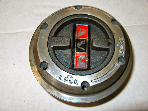
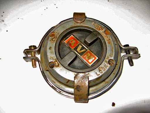
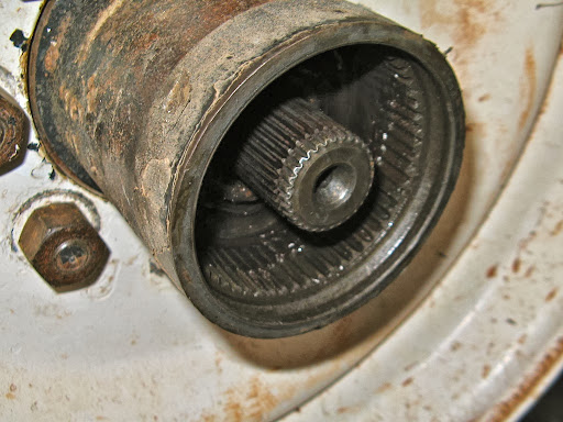
    The AVM Model 439 Free Wheeling Hub for 30 spline shafts

    dbb6ce89-2012-02-11-19-31.jpg

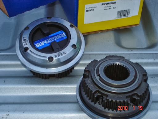
    If you have SuperWinch Free Wheeling Hubs like this, you will probably also have the same problems. They look like rebadged AVM's and I know of one which is stamped with the same casting number, 439. The SuperWinch part number is 400439.
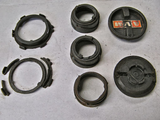
    AVM Hub Components

    The AVM hubs comprise 2 main assemblies, an outer bolt-on assembly which contains the Free/Lock controls and a sliding locking ring, and an inner gear which engages the internal hub splines and drives the hub round and also holds the splined drive shaft roughly central.

    Outer Assembly

    The outer assembly comprises an aluminium outer frame, a plastic control lever, a grooved plastic cylinder, a large spring and a steel locking ring. It bolts on to the inner assembly via 6, 2 inch long countersunk socket head screws.

    1fc58466-2012-02-11-19-31.jpg

    The locking ring and spring behind the outer assembly shown in the Lock (expanded) position

    The locking ring is attached via a spiral spring to a plastic ring with 3 tangs on it to engage in the grooved cylinder and it's alignment is maintained by 2 thin roll pins inserted into the aluminium frame.
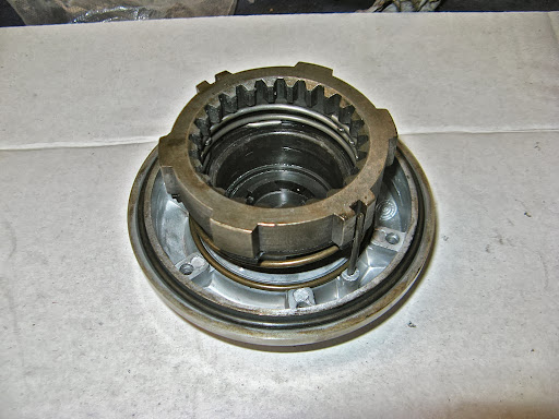
     

    Inner Assembly


    The inner assembly comprise a solid steel ring casting with external splines held in by a large internal circlip inside the hub, plus a central spline gear which is free to rotate but is held into the larger ring by a rear circlip. It is also held in by a circlip around the front of the central splined drive shaft.

    df43c237-2012-02-11-19-31.jpg

    The rectangular cams and gear teeth on the locking ring on the outer assembly on the left (shown in the retracted Free position) engage with the inner gear assembly on the right to lock the hub

    ff852f41-2012-02-11-19-31.jpg

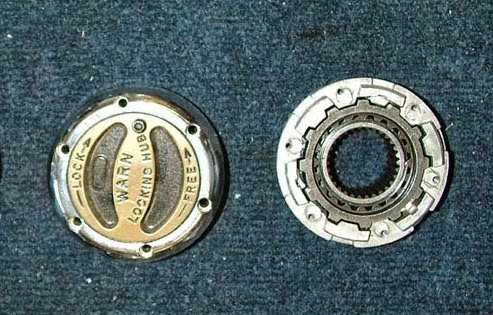
    Warn use similar locking ring and fixing screw principles

    Hub Operation

    When the lever is moved to the Lock position, the cylinder is rotated by the control lever and the tangs on the locking ring slide down the grooves. The spring expands pushing the locking ringing into the inner assembly, locking the splined central shaft to the outer hub by engaging the gear teeth and the ring of 6 rectangular cams.


    The natural or fault position of the control is the Locked position and turning the lever to the Free position actually pulls the locking ring away from the inner gear. Indents on the grooved cylinder hold it locked or unlocked.


    No maintenance is normally required, but if they are removed, cleaning the plastic surfaces and lightly oiling them will maintain smooth operation. Also oil the central splined gear where it rotates continuously inside the back of inner assembly.

    Failure Modes


    The inner mechanical components of the AVM hubs are solid and strong I have never had a problem or concern with the mechanics of its operation. If anything there ever broke it would indicate something far more seriously wrong with the stub axle/spindle or bearings than the free wheeling hub. However anything can break and I have seen the equivalent locking ring broken on Superwinch and Warn hubs.


    The outer assembly is held in by 6 long 8/32 UNC screws into the inner assembly and these screws can come loose, since they have no locking mechanism, potentially causing the outer assembly to fall off.


    Without outer assemblies fitted, the vehicle can only operate in 2 wheel drive as there is no locking ring to couple the splined shaft to the hub. [OK, with a diff lock, 3wd is theoretically possible].


    The inner gear components are held in by 3 separate circlips so it's very unlikely they can come out in operation. They contain no plastic or weak components so it's a very strong mechanism.


    The plastic control components in the outer assembly however are weak and poorly designed and it is these that are most likely to cause a failure.

    3fc593f9-2012-02-11-19-31.jpg

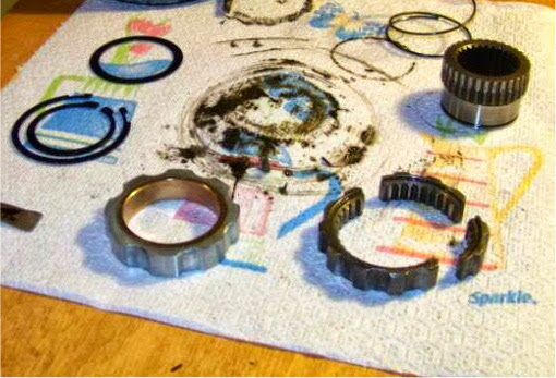
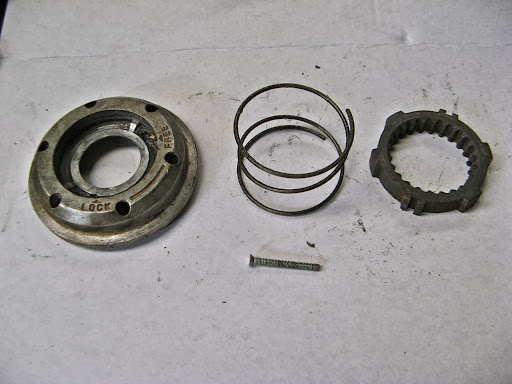
    The plastic parts that can break. The ring with tangs, the grooved cylinder and the control lever

    In my experience the primary problem is the tangs on the plastic ring which either wear away or break off. This leaves the hub either unable to engage or disengage 4WD, or, when one tang breaks off, the hub is left partly engaged and clicking as the wheel rotates. There is only a 90º turn in the control mechanism (unlike Warn's 325º) which puts a strain on the plastic tangs.


    2c26830c-2012-02-11-19-31.jpg

    2 broken plastic rings. The top one is complete except for one broken tang. The lower one has all three tangs but the sides are shattered.

    The grooved cylinder can also wear so the indents no longer keep the hub in the selected position and/or the clips on the inside of the control lever fail to hold the grooved cylinder so that control is lost. The hub may then become locked, even though the lever looks like it's in the Free position. This is a "fail-safe" situation (ie 3 or 4wd) but can catch you out if you are not aware of it. Where this is suspected, I turn the front drive shaft by hand until I know what's engaged or not.


    I've addressed the problem of fragile components with AVM in Brazil and asked if there are stronger "plastic" parts or spares available and this was their response:


    Dear Mr.Ribbans,


    really the nylon pieces are the weakest of hub components and might last  just 6/7 years in standard conditions of use . We do not sell internal components to avoid installation faults and safety problems. Therefore we commercialize just the  service kit shown in the attached picture and the  nylon cap dial. Anyway please contact our local distributor at broach@donkyatt.com.au and ask him  if  can import the complete nylon set ( 3 pieces) . In that case we will do an exception for you  and supply it. 

    thank you


    Export dep.


    I've contacted Don Kyatt and they are looking into the availability of spares components.


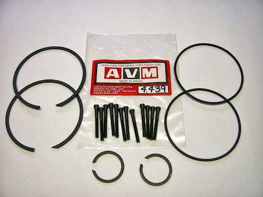
    The "service" kit (AVM #4.439) comprises only 2 sets of replacement screws, large O-rings and circlips for the inner hub and splined shaft, which is pretty useless.


    153e6973-2012-02-11-19-31.jpg

    AVM 4.439 Service Kit

    Faults on other makes of hubs


    Although Warn is touted as a superior make, a brief search indicates there are cases of failures in their hubs too, but their problems seem to be mainly shattered locking rings rather than the control mechanism. The Warn locking ring appears to be slightly thinner than the AVM equivalent but has more cams.


    f545b0b5-2012-02-11-19-31.jpg


    ab0b4a22-2012-02-11-19-31.jpg


    5d2f6135-1-2012-02-11-19-31.jpg

    What to do if a FW hub fails


    In an outback situation, loss of 4wd is the most important consideration but can be easily prevented or rectified with a few precautions and/or some critical spares:

    Firstly it is obviously preferable/essential that the the outer hub never falls off since it contains the all important locking ring, without which 4wd is not possible. (We were on a bitumen road to Melbourne when ours disappeared so it can happen at any time).


    The outer hub is fixed by 6 screws which are 2 inch long (possibly 8/32 UNC) countersunk socket headed and deeply recessed into the aluminium frame. If they are over tightened or Loctited to avoid them loosening they can be very difficult to remove and I've had to drill several out. The heads are either small Allen sockets, which round off very easily, or Torx sockets which are easier to remove.


    [Note: to remove a stubborn or rounded Allen head screw, you can hammer an equivalent sized Torx driver into the Allen socket to improve the grip, the sharp points cut their own shape. If you must reuse a damaged screw, cut a slot in the head first so a flat bladed screwdriver can be used for later removal].

    Screws and the outer hub can be retained by several means (suggested by Oka Owners Group Members):

    • Loctite the long fixing screws. This will work but makes their removal potentially difficult and might mean drilling them out.
    • Put tape over the heads of the screws so they can't come out, or if they try too it's easier to spot.
    • 90a002fd-2012-02-11-19-31.jpg
  • Screw heads held captive by aluminium tape
  • f9cdbd49-2012-02-11-19-31.jpg

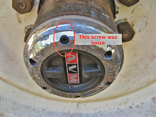
    After removing the tape 9,000 km later, 2 screws were loose and this one would have fallen out, but for the tape holding them in.

    • Fill in the holes above the heads of the screws with silastic. This will work but it's also potentially difficult to remove.
    • Drill and re-tap the screw holes on the inner gear and aluminium frame to allow larger bolts and lock washers to be used with bigger Hex or Allen heads that you can actually get a spanner on. A short spacer will also be required to fill the countersink bore. Two larger bolts would probably suffice to retain the hub and M5 is probably the largest bolt size that could be fitted. M6 might exceed the space available and interfere with the internal circlip. These bolts could then be Loctited successfully since removing them is mechanically easier. This is probably most effective but invasive solution and doesn't affect wheel removal.
    • Bolt a strip of steel/aluminium across the front of the aluminium frame to prevent it from falling off, and secure the strip on to the hub steps, if fitted, or to the hub using a large hose clip or even a large tie-wrap. However this might impede operation of the control lever.
    • Fabricate a steel ring clamped to the hub (or use the step ring where fitted), with 2 or more claws welded around it which fit out and over the hub screws to retain them and the outer assembly. The claws will not impede access to the control lever and the ring can double as a non-slip step ring. A thin flat ring could be welded to the ends of the claws to retain all the screws and avoid them catching on passing flora. I'm implementing this concept and incorporating hub steps.

    8c87b4a1-2012-02-11-19-31.jpg

    Prototype claw clamp/step ring retention method

    ade8343f-2012-02-11-19-31.jpg

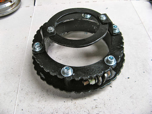
    The final design incorporating non-slip step rings

    f89040db-2012-02-11-19-31.jpg

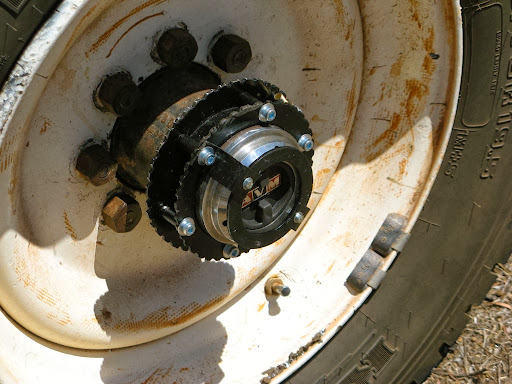
    Hub step in operation with FWH retention ring

    06c3f7cf-2012-02-11-19-31.jpg

    The control lever is still accessible (CW to lock, CCW to unlock)

    In this design the clamp ring is a 2mm x 25mm steel band but the steps are 3mm aluminium plate because it's easier to work with and lighter. 3 steps rings could be used á la Oka, but I'm not sure the inner ring is very useful.

    776d7d70-2012-02-11-19-31.jpg

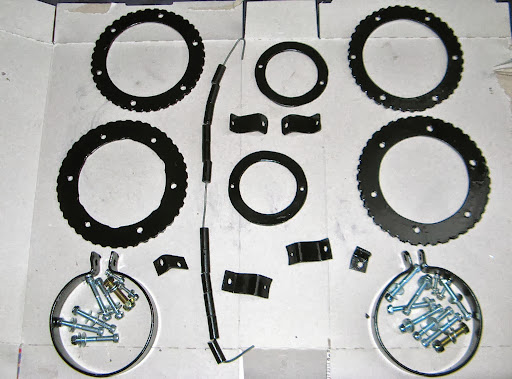
    Step ring and retention ring components

    The step rings are clamped either side of the steel clamp band by long bolts and spacers so they can't move laterally. A small bracket secures the rings to the clamp band bolt so they can't rotate.

    Secondly, in the event that the outer assembly does fall off without trace, or if its internal components fail, there is still a quick and easy way to engage 4wd as long as you have a few critical components available:

    • Either a complete spare outer hub assembly (obviously) or,
    • Parts from a failed outer hub assembly:
      • the aluminium frame (the alignment roll pins are not necessary and could be removed),
      • a locking ring,
      • the large spring, and
      • a few of the long screws.

    These items can be recovered from previously failed hubs and/or are not heavy items to carry as spares.

    1c601f24-2012-02-11-19-31.jpg

    Components needed to engage 4wd

    To lock the hub into 4wd, insert the locking ring, bevelled edge first, into the inner hub gear and bolt the aluminium frame on to the hub, compressing the large spring between them. Only a minimum of 2 or 3 screws are required to hold the outer frame on since there's not a huge force against it, and in 4wd, all the hub components rotate together. Put some tape over the screw heads so they can't come loose.


    This can be done in a few minutes since no wheel removal or jacking is required, and the centre hole on the frame can be covered by sticky tape to keep dust out.


    Just a locking ring alone would suffice if you could engineer a way of holding it into the hub, eg screwing a plate or strip across the hub securing it with the long fixing screws, but if you've got a locking ring, you've probably also got an aluminium frame.

    To revert to 2wd, remove the locking ring and spring and replace the aluminium frame.

    63c500ca-2012-02-11-19-31.jpg

    The outer frame and spring push and hold the locking ring into the inner gear assembly, locking the hub

    What other precautions can be taken?

    The inner assembly is held in place by a large circlip which sits in a lipped groove in the hub, behind which is a bevelled edge prior to the internal splines. It is therefore possible and desirable to fit 2 circlips.

    2a800f2c-2012-02-11-19-31.jpg

    The groove is wide enough for 2 circlips to hold in the inner assembly

    The reason is as follows. The locking ring begins to engage the inner gear when the spacing from the outer hub face to the inner gear face is about 6mm. This very close to the normal unlocked separation of the inner gear and locking ring, which is why a single broken tang can cause clicking. The long screws actually draw these faces together when tightened and anything that can increase the spacing minimises this problem. Fitting 2 circlips will achieve this.

    It has been also suggested that the length of the splined shaft gear or location of the circlip groove can affect operation of the hub, but in my case, I could not see any way that the gear or shaft could impact the plastic components. The drive shaft position is controlled by the thrust surface on the rear of the wheel hub and the ends of the splines remain about 10mm from the control components. Of course replacement or other makes of drive shaft may have different lengths and the circlip maybe in different locations along the shaft.


    If the central spline gear seems to be too long, don't fit the circlip on the splined shaft, it can't go far and the gear should still be held to the inner assembly by a rear circlip. Others have machined the gear shorter to allow fitting of the circlip but that depends on the length of the drive shaft which I assume might vary between makes.
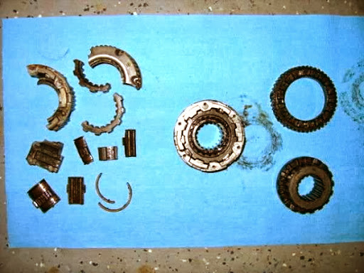
     

    Spare Parts


    I have had around 3 or 4 failures of AVM hubs, all resulting from broken plastic parts, plus one lost outer assembly caused by screws working loose, and twice I've had to buy replacement sets. So I now have a stash of spare parts which can be re-assembled into useable spares.

    2fd66ad0-2012-02-11-19-31.jpg

    My pile of AVM free wheeling hub spares, not including the 2 on the Oka

    095df14b-2012-02-11-19-31.jpg 

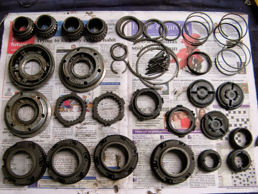
    All the mechanical components are reusable, but very few of the plastic parts are

    On most of our trips I have had to do some repairs to the hubs so on our next desert trip I shall be taking:

    • a complete outer assembly rebuilt out of spare parts,
    • a complete inner assembly,
    • 2 spare locking rings and large springs,
    • a spare aluminium frame,
    • several spare fixing screws (plus Allen/Torx keys),
    • spare circlips (they can ping off and get lost), and
    • spare plastic components (if AVM/Don Kyatt come good).

    Disassembly or Repair of the Outer Hub Assembly


    If you need or want to disassemble/reassemble the outer hub there are few things to be aware of.


    The control lever is held to the grooved cylinder by 2 thin clips on the back of the control lever. When these are locked together, the locking ring and the spring are all held compressed.

    To remove the control lever, use a round bar (I used a socket extension bar) held against the inside to the lever and give it a sharp tap. It should pop out and all the components can then be removed.

    To reassemble the outer hub, note that the control lever has 2 slots on the rear which engage the 2 tabs protruding from the grooved cylinder. These tabs are not the same width and must be oriented correctly so the Lock/Free positions line up. Refer to the photo of plastic items above.

    Also the grooved cylinder can be oriented in 3 different positions on the tangs so ensure that it is correctly aligned so that when engaged with the operating lever, the Lock/Free positions are correct.

    When the components are correctly aligned, holding them all compressed on to a solid surface, use a socket which will just fit inside the cylinder and tap it to engage the control lever clips. If one tap is not enough, check the alignment of the control lever with the grooved cylinder tabs.

    Note, each time this is done, or if the parts are not aligned properly, there is a risk of the plastic edges breaking away, eventually causing them to fail, so don't do this too often. I have successfully done this a few times, to construct a working outer hub from components from several failed hubs but they are not designed to be disassembled.

    Oil the plastic parts lightly to minimise wear and allow them to slide smoothly.

    Differences in Hub Design


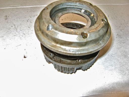
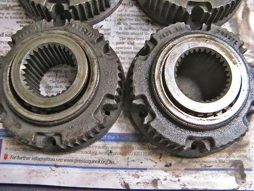
    When rebuilding a spare inner hub, I observed that there are difference in the design of the outer ring.


    Both types are marked 439, which is the AVM part number for a hub to suit a Dana 60 internal mounting and 30 spline shafts.


    1c314591-2012-02-11-19-31.jpg

    Note the opening (not the spine gear) in the rear of the inner ring on the left is larger than the one on the right.

    The inside diameter of the left hand gear is 50mm whereas the right hand one is only 49mm. Although it doesn't sound much, the inside surface of the outer ring, which rotates continuously with the wheel, is what supports the splined gear, which is stationary in 2wd, and 1mm can make a difference. On the larger ring, the spline gear almost falls through the hole.


    I suspect the larger ones are early models since all our later models have been the 49mm size.


    5a7b8f37-2012-02-11-19-31.jpg

    Both rings are stamped "439"

    For reference, AVM also make a similar hub for 35 spline shafts, model 439K, which is the model recommended for the Oka NT and is listed in their catalog. The 30 spline model 439 is listed under Ford F350, Dana 60.